Rose Window
Spec finalized 2026-05-18. WS2815 12V on dedicated 12V PSU — no converter needed.
Physical facts
| Diameter | 4.877m (~16 ft) |
| Circumference | 15.3m |
| Position | Center of front facade, Z = 3.1–8.0m, faces inward toward dance floor |
| Petals | 18 ordered — 16 installed + 2 spares. Each removable, each its own independent LED strip. |
| Cells per petal | 14 (individual Gothic tracery openings) |
| Total addressable pixels | 224 |
LED strip
| Property | Value |
|---|---|
| Chip | WS2815 |
| Density | 60 LEDs/meter |
| Voltage | 12V (dedicated 12V PSU — see Power below) |
| IP rating | IP65 — conformal coating only, not silicone sleeve |
| Protocol | WS2811-compatible, dual data line |
| Why WS2815 | Dual data line = breakpoint resume. Window is hard to service on playa. 60px/m at 12V = 1 pixel per LED. Widely available, well-proven. |
| Why IP65 coating | Alex: silicone sleeves (IP67/68) trap heat on playa. Conformal coating only — not encased. |
| Why 60/m | Finer tracery geometry needs higher resolution than arches/spires. |
| Why 12V not 24V | WS2815 is 12V-native — correct voltage for the chip. Rose window runs on its own 12V PSU; rest of install is 24V. F48V5 differential signal is power-independent, so mixed voltages across SmartReceivers work fine. |
| Why not buck converter | Dedicated 12V PSU is simpler and more reliable than a converter. Each zone is self-contained. |
Quantities
| Item | Value |
|---|---|
| Path length per petal | 8,372mm (8.37m) — measured in Illustrator |
| LEDs per petal | ~517 (514–517 calibrated) |
| Strip length ordered per petal | 900cm — ~63cm margin for real-world variation and connector leads |
| Strip length per petal | 1 × 9m custom strip (ordered from Ray Wu’s Store — pre-terminated with xConnect) |
| Total strips | 18 (16 installed + 2 spares) |
| Total LEDs | ~9,036 |
Custom 9m lengths ordered from Ray Wu’s Store (AliExpress) with xConnect connectors pre-terminated at the factory. No mid-petal join needed.
Cell diagram
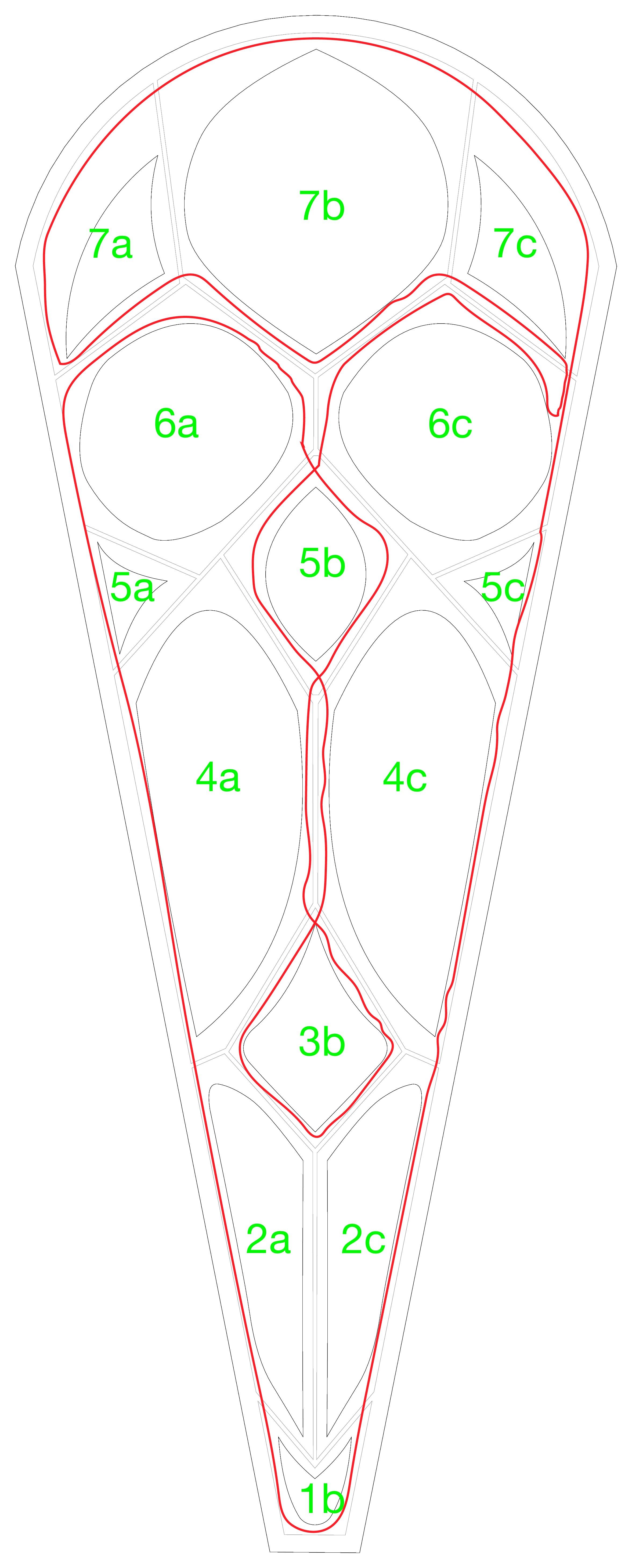
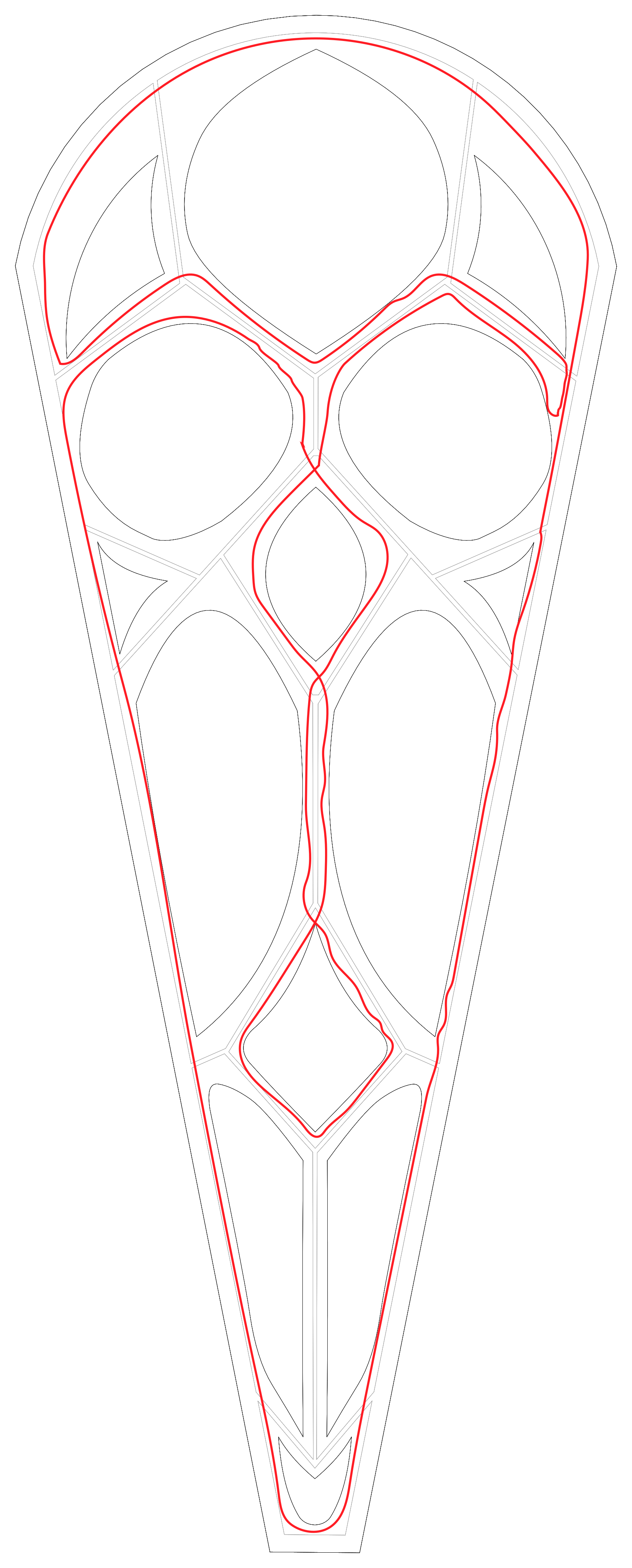
📄 Download petal-combined-path-v3.svg — full framing + tracery with LED routing path.
Cell naming — airplane-seat style
Rows 1–7 bottom-to-top. b = center/spine, a = left, c = right. 2-cell rows skip b.
| Row | Cells | LEDs | Description |
|---|---|---|---|
| 7 | 7a, 7b, 7c | 36 + 50 + 36 = 122 | Top: left arch, center circle, right arch |
| 6 | 6a, 6c | 38 + 39 = 77 | Two large circles |
| 5 | 5a, 5b, 5c | 10 + 43 + 10 = 63 | Small connectors + center vesica |
| 4 | 4a, 4c | 48 + 48 = 96 | Two large ovals |
| 3 | 3b | 43 | Diamond/kite (spine) |
| 2 | 2a, 2c | 27 + 28 = 55 | Lower narrow cells |
| 1 | 1b | 21 | Bottom rounded cell |
Full pixel address example: P03-5b = petal 3, center vesica cell. Petals P01–P16 clockwise from 12 o’clock.
Animation groupings
| Group | Cells | LEDs |
|---|---|---|
| Spine | 1b + 3b + 5b + 7b | 21 + 43 + 43 + 50 = 157 |
| Left side | 2a + 4a + 5a + 6a + 7a | 27 + 48 + 10 + 38 + 36 = 159 |
| Right side | 2c + 4c + 5c + 6c + 7c | 28 + 48 + 10 + 39 + 36 = 161 |
| Top cluster | 7a + 7b + 7c | 36 + 50 + 36 = 122 |
| Big ovals | 4a + 4c | 48 + 48 = 96 |
| Big circles | 6a + 6c | 38 + 39 = 77 |
Initial LED mapping
The image below shows the actual LED positions along the strip routing path for one petal — ~517 LEDs sampled at 60/m, color-coded by cell. The strip connector sits at the 1b/2a boundary (bottom center), tucked behind the central tracery.
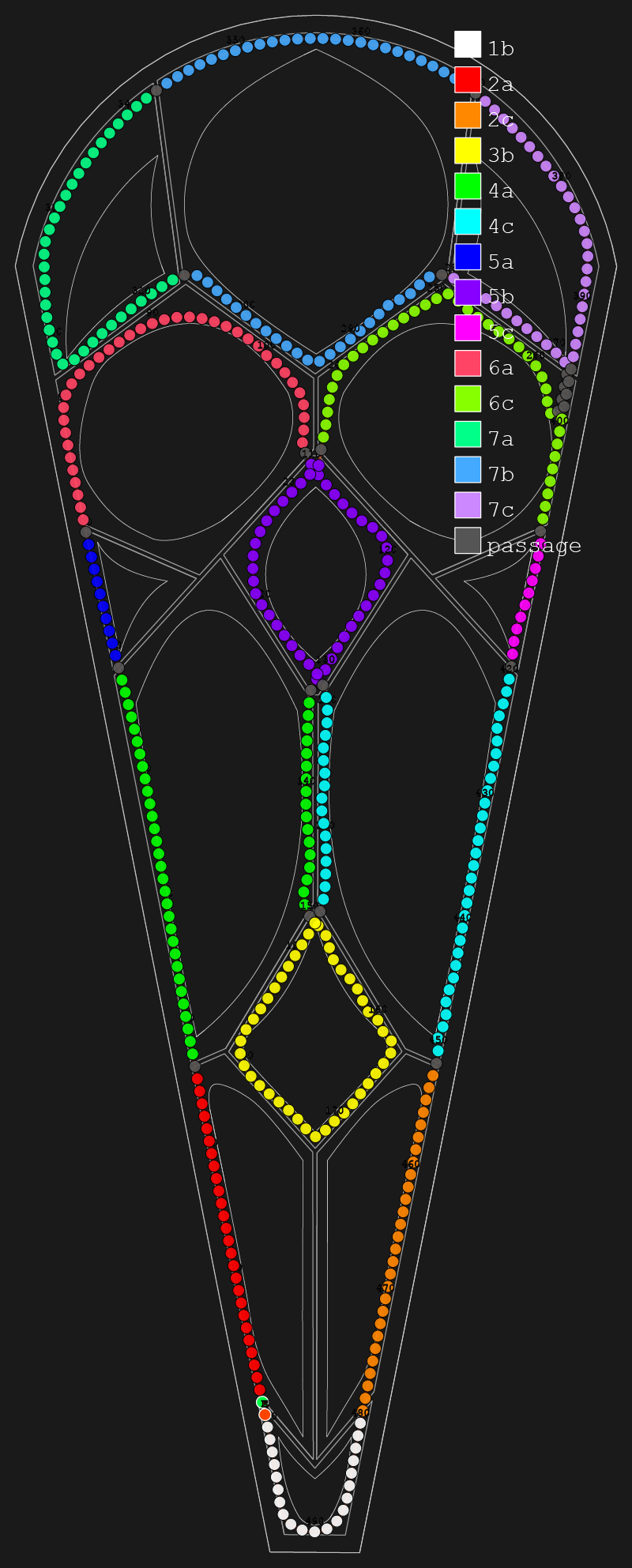
Source files in gothic-folly-leds/pixel-map/ — see petal-config-v2.json for cell segment boundaries and visualize-petal-v7.py to regenerate.
Arduino tester
A standalone Arduino-based tester for installing and calibrating individual rose window petals. It drives the full petal strip without needing the Falcon F48V5 or FPP — useful at a workbench or in the metal shop during install.
Hardware
| Component | Details |
|---|---|
| Microcontroller | Any 5V Arduino (Uno, Nano, etc.) |
| Power supply | 12V PSU (e.g. Mean Well LRS-250-12) — powers the LED strip |
| Data pin | Arduino pin 6 → strip DIN |
| Ground | PSU COM → strip GND and Arduino GND (shared) |
| BIN (backup data) | Leave unconnected during testing |
| Arduino power | USB only — do not connect Arduino VIN to 12V |
LRS-250-12  +12V ──► LED strip +12V
LRS-250-12  COM  ──► LED strip GND + Arduino GND
Arduino pin 6    ──► LED strip DIN
Arduino          ──► powered by USB only
Software
Requires the FastLED library. Upload petal-test.ino via Arduino IDE, then open Serial Monitor at 9600 baud.
Serial commands
| Command | Effect |
|---|---|
c | Cell colors — each of the 14 cells lights a distinct color. Use this to check that cell boundaries match the physical aluminum structure. |
m | Markers — every 5th LED dim white, every 10th LED bright yellow. Use this to count LEDs and locate boundaries precisely. |
b | Blue sweep (default on boot) — a blue/purple wave sweeping hub → rim |
s | Sweep — full-color wave |
p | Pulse — cell colors breathing |
+ / - | Brightness up / down |
The sketch is pre-loaded with P01’s cell segment boundaries (517 LEDs). If another petal has a different total LED count, update NUM_LEDS before uploading. See Petal Calibration below for the full adjustment workflow.
Petal calibration
Each petal strip is calibrated after install to confirm that cell boundaries in the LED data match the physical aluminum structure. Small shifts of 1–3 LEDs are expected — the strip doesn’t always land in exactly the same position cell-to-cell. Calibration records the real layout per petal so the xLights model, simulator, and controller all reflect the actual physical wiring.
The source of truth is pixel-map/petal-config-v2.json. The default_segments entry reflects petal P01. Any petal that differs from P01 gets a petal_override entry. Everything downstream — xLights, the 3D simulator, FPP on the F48V5 — is regenerated from this file.
P01 was initially installed with a temporary unsheathed strip (used while awaiting the Ray Wu AliExpress order). It will be re-calibrated last once the final IP65 strip is in. Current default_segments are from the temporary P01 install and serve as the baseline for all other petals.
Cell color cheat sheet
When testing with the Arduino tester in c mode (cell colors), each cell lights a distinct color:
| Cell | Color | Cell | Color |
|---|---|---|---|
| 2a | Red | 6c (×2) | Violet |
| 4a (×2) | Green | 7c (×2) | Lavender |
| 5a | Cyan | 7b (×2) | Teal |
| 6a | Purple | 7a | Amber |
| 5b (×2) | Blue | 5c | Blue-violet |
| 3b | Yellow | 2c | Orange-red |
| 4c (×2) | Sea-green | 1b | White (hub) |
Cells marked ×2 are visited twice by the strip — same color on both passes. Small dark gaps are normal (8 passage LEDs stay dark at connector/threading points).
Calibration workflow
- Connect petal strip to the Arduino tester (see
arduino/petal-test/petal-test.ino) - Send
c— cell colors appear based on the P01 default segments - Walk the strip path in order and check each color change against the physical cell boundary:
2a → 4a → 5a → 6a → 5b → 4a → 3b → 4c → 5b → 6c → 7c → 7b → 7a → 7b → 7c → 6c → 5c → 4c → 2c → 1b
- If all boundaries match → petal uses the default, no override needed
- If a boundary is off → switch to
mmode (every 5th LED dim white, every 10th bright yellow) and count the shift; report the offset and Claude updatespetal-config-v2.jsonwith apetal_overrideentry - After all 16 petals are confirmed, run the full rebuild pipeline to propagate the updated layout everywhere
See petal-calibration.md in the project root for the full step-by-step session guide.
Simulation plan
The goal is a real-time on-screen simulator so we can preview and design animations before (and during) the event — without needing the physical structure running.
Phase 1 — Pixel position database Build a structured map of every addressable pixel keyed by zone, petal, and cell, with SVG/screen coordinates. The rose window petal mapping above is the first piece. Other zones (spires, arches) will follow as hardware is finalized.
Phase 2 — Static pixel map A full-structure SVG or browser canvas showing every pixel at its physical position, color-coded by zone and cell. The petal visualization is the prototype.
Phase 3 — Real-time E1.31 simulator A browser-based renderer that listens for E1.31 (sACN) UDP packets from the Falcon F48V5 (or from FPP/xLights) and draws each pixel at its mapped screen position in real time. This lets us:
- Preview xLights sequences before mounting hardware
- Test TouchDesigner live-reactive patches
- Visualize Ableton-synced BPM effects
- Debug universe/channel assignments
Power
WS2815 at 60/m draws ~18W/m max at full white.
| Per petal (9m max) | ~162W |
| 16 active petals, full white | ~2,600W |
| Typical show brightness (20–40%) | ~520–1,040W |
PSU: 2× Mean Well HLG-320H-12 (320W, 12V, IP65) wired in parallel gives 640W — covers typical use comfortably. Add a third unit for full-white headroom or use HLG-480H-12 (480W) units instead.
The rose window PSUs are completely separate from the 24V distribution used by the rest of the installation. No converter needed. The F48V5 differential signal to each SRx1 is power-independent.
Controller — one petal per dedicated port (4× SRx1)
Decided + bench-confirmed 2026-07-13. Each petal is ~517 physical pixels. Falcon pools the 704-px/port cap across the sub-address banks of a chained receiver, so a single SRx4 (16 outputs on 4 ports) would put 4 petals on one 704-px port — 4 × 517 = 2,068 ≫ 704, impossible. No two petals can share a port. Fix: 4× SRx1 (un-chained), one on each of 4 Cat6 runs, ports 33–48 — 16 petals, 16 dedicated ports, 517 of 704 each. The former single-SRx4 plan is superseded (the SRx4 is freed).
Hardware
| Item | Details | Source | Price |
|---|---|---|---|
| SRx1 SmartReceiver ×4 | 4 outputs each = 16; one petal per dedicated port (ports 33–48) | pixelcontroller.com | ~$40 ea |
| Falcon F48V5 | Main controller (shared with full installation) | pixelcontroller.com | $270 |
| Mean Well HLG-320H-12 (or HLG-480H-12) | 12V PSU, IP65, dedicated to rose window | Amazon / TRC Electronics | ~$80–120 each |
| Thermal interface tape, 1mm | Between strip PCB and aluminum framing | Amazon | ~$10 |
SRx1/SRx4 ↔ F48V5 compatibility confirmed by David Pitts (pixelcontroller.com), 2026-05-13. The one-petal-per-port capacity was bench-confirmed 2026-07-13 (a single 517-px petal lit fully on one SRx1 output, no smart-mode clipping).
Wiring
F48V5 controller
    │
    ├── Cat6 #1 (ports 33–36) ──► SRx1 (ID A) ─┐
    ├── Cat6 #2 (ports 37–40) ──► SRx1 (ID A) ─┤  4 SRx1s, co-located
    ├── Cat6 #3 (ports 41–44) ──► SRx1 (ID A) ─┤  in one hub enclosure
    └── Cat6 #4 (ports 45–48) ──► SRx1 (ID A) ─┘
                                      │
                        16 outputs (4 per SRx1), one petal each
                                      │
                        ┌─────────────┴──────────────┐
                      Petal 1 ... ... ... ... ... Petal 16

Power (rose window only — isolated from 24V distribution):
12V PSU ×4 (HLG-320H-12) ──► one per SRx1 ──► 16 petal strips (WS2815 12V)

Rest of installation:
24V PSUs ──► all other SmartReceivers
Hub wiring (as built): the four SRx1-PSU boards co-locate in the rose hub enclosure beside the window; four Cat6 runs come up the tower scaffold from the controller. Each petal gets a 20 ft xConnect data lead from its dedicated output, and four 12 AWG / 15 A DC trunks run to the rose center, where the 16-way splitters (soldered onto the trunk ends, branches labeled 1–16) fan power out to the petals. All boards installed and bench-tested on the real window.
What to order
See the Shopping List for all items — ordered, arrived, and pending.