Build Guide
This section is the playa binder. It tells you how to build and wire every Satellite Receiver (SR) box, which cable plugs in where, and where the power comes from. Print it and bring it — every page is designed to be readable on paper in the sun.
- SR Boxes — one page per box — the heart of the guide. Find your box, see exactly what plugs into it.
- Cables & Runs — every network cable route and the cable order list.
- Power Map — every power supply: its letter, where it sits, what it feeds.
How to read these pages (2-minute primer)
Box names
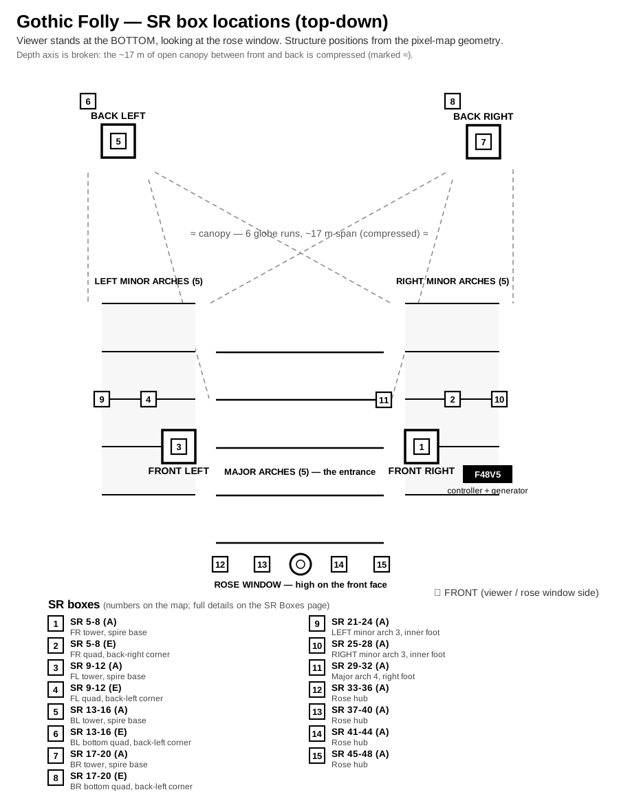
Every SR box has a name like SR 5-8 (E). That means: this box handles controller ports 5 through 8, and its ID dial is set to E. The name is printed on the box and used everywhere — labels, tables, diagrams. If a cable label says From SR 5-8 (E) • No.1, walk to the box marked SR 5-8 (E) and plug into socket 1.
The letter dials (why boxes have letters)
One network cable (Cat6) carries 4 “ports” of lighting data. Several SR boxes can share that same cable in a daisy-chain — each box’s ID dial is set to a different letter (A, E, …) so each box takes its own share. You never need to think about this while wiring: just set the dial to the letter in the box’s name and plug the chain in the order the box page says.
Cable labels
Every cable end has a printed tag. The tag’s big text matches either a socket on an SR box (e.g. 5A) or a junction number. Match tag to socket/table row and plug in. If a tag doesn’t match anything on the box page in front of you, stop and check the Box Directory — you may be at the wrong box (some boxes look identical).
⚡ The one power rule everyone must know
LED power never comes from the SR box (the rose window is the only exception). The SR sends the data signal only. Every strip and string gets its power (V+) from a fused power bus connected to a power supply. Inside each enclosure that’s already wired — but if you ever find yourself connecting a V+ wire to an SR board output on a 24 V zone: stop, that’s a mistake. The box pages spell out where each zone’s power really comes from.
Colors and voltages
| Zone | Voltage | LED power path |
|---|---|---|
| Arches, spires, quads, canopy | 24 V | Fused bus from a 24 V power supply — never the SR |
| Spirelets + wash floods | 12 V | The tower’s dedicated 12 V flood supply |
| Rose window | 12 V | Through its SRx1 (near end) + far-end tap — the one exception |
Wire & fuse gauges — which gauge goes with what
Everything falls into two tiers by current. When in doubt, go thicker (a lower AWG number) — a heavier wire or holder is always safe; too-thin is the only danger. The fuse protects the wire, so the fuse must never exceed what the smallest wire in that run can carry.
| Tier | Fuse | Inline-holder gauge | V+ hookup wire |
|---|---|---|---|
| Heavy | 15 A | 10 or 12 AWG | 12 AWG |
| Light | ≤ 7.5 A | 16 AWG | 16–18 AWG |
Fusing chart — every fuse in the build, by amperage
All inline holders are the Shimeyao waterproof ATC/ATO sets ordered 7/30 (96× 16 AWG · 48× 12 AWG · 24× 10 AWG). Fuses: Chanzon 100× 5 A, dedicated 15 A packs, and the SIM&NAT 130-pc kit for the 2 / 3 / 7.5 A values.
| Fuse | Circuits | Count | Fuse stock | Holder (ordered) |
|---|---|---|---|---|
| 15 A | Quad SR-corner taps ×6 · quad far-corner taps ×4 · rose-centre trunks ×4 | 14 | 15 A packs (+ kit) | 12 AWG |
| 7.5 A | Front wash chains ×2 · A-panel canopy feeds ×2 · spire groups ×4 + A-panel spire feeds ×2 (re-fused 5→7.5 A for the 80% cap, 08-06) | 10 | SIM&NAT kit | 16 AWG |
| 7.5 A | A-panel 12 V flood feeds ×2 (12 AWG runs — match the wire) | 2 | SIM&NAT kit | 12 AWG |
| 5 A | Back wash ×2 · minor pigtail V+ ×10 · minor injections ×20 · pod branches ×18 · arch-4 pair ×2 · rose petal far ends ×16 | 68 | Chanzon 100-pk | 16 AWG |
| 3 A | Canopy taps ×6 | 6 | SIM&NAT kit | 16 AWG |
| 2 A | Spirelet groups ×8 · SR board power (flood-rail boxes) ×6 · buck inputs (24 V-only boxes) ×5 | 19 | SIM&NAT kit | 16 AWG |
| Total fuse positions | 119 |
Holder stock check: 16 AWG positions total 103 vs 96 ordered — the last ~7 light circuits ride spare 12 AWG holders (thicker is always fine). 12 AWG: 16 of 48 used; 10 AWG: all 24 are spares/upgrades. Fuse stock check: confirm the kit + packs cover 15 A ≥ 14, 7.5 A ≥ 12, and 2 A ≥ 19 (the SIM&NAT kit carries ~10–15 per value — top up 2 A and 7.5 A if short). 5 A: 68 of 100 ✓.
Substitution rules if a size runs short:
- 7.5 A position → 10 A (wire is 16 AWG or heavier — still protected; going down to 5 A would nuisance-blow spires/wash at high brightness).
- 2 A position → 5 A (Chanzon stock is deep; loads are ≤1.7 A real and the wire is protected with huge margin — save the scarce 3 A blades for the canopy taps).
- The ceiling stands: never put anything above 10 A in a 16 AWG holder, and never substitute above the chart value elsewhere.
Arch foot pigtails that carry a whole leg (major arch ≈ 7–10 A) use heavier 12–14 AWG wire — see the per-box wiring sheets and the power-tap-pod sheet.
Data cabling (not fused): controller → SR = Cat6; SR → fixture = 3-core xConnect (18 AWG); rose petal data (SR box → centre, ~4 m) = 3-pin xConnect leads.
This is the quick reference; the authoritative per-socket fuse value for each box is printed on its SR Boxes sheet.
Printing the binder
Print straight from the browser (⌘P / Ctrl-P) — the pages carry print styles: site navigation disappears, everything goes black-on-white at sunlight-legible sizes, and on the SR Boxes page each box starts on its own page, so the whole binder is one print job. Print the overview map separately as the cover sheet, plus the Power Map and Cables pages.
If something looks wrong
Don’t improvise a fix at the box. Note the box name, the socket, and the cable tag, and raise it — the wiring database is the single source of truth, and a mismatch means either a mislabeled cable or a real error that must be fixed there, not patched in the field.
Where these pages come from: the box pages and labels are generated from the wiring database (
wiring-db/strands.db), which is machine-checked against the controller configuration. Decision history lives in the project’sprocess_notes.md, not here.