SR Boxes — Build & Wiring, One Page Per Box
⚙️ GENERATED PAGE — do not hand-edit. Built from the wiring database (
wiring-db/strands.db) bytd/generate-build-docs.py. The database is machine-checked against the controller config on every regen (pixel-map/validate.py). Found an error? Fix the database, re-run the generator, and the labels + this page stay in sync.
New here? Read How to read these pages first — it explains the box names, the letter dials, and the one power rule everyone must know.
Box directory
| Box | Board | Where | Drives |
|---|---|---|---|
| SR 5-8 (A) | SRx4 | Front-Right Tower — spire base (top of tower) | 14 cables |
| SR 5-8 (E) | SRx2 | Front-Right Tower — low corner — back-right corner of the quad arch | 5 cables |
| SR 9-12 (A) | SRx4 | Front-Left Tower — spire base (top of tower) | 14 cables |
| SR 9-12 (E) | SRx2 | Front-Left Tower — low corner — back-left corner of the quad arch | 5 cables |
| SR 13-16 (A) | SRx4 | Back-Left Tower — spire base (top of tower) | 14 cables |
| SR 13-16 (E) | SRx1 | Back-Left Tower — back-left corner of the back-bottom quad arch | 1 cable |
| SR 17-20 (A) | SRx4 | Back-Right Tower — spire base (top of tower) | 14 cables |
| SR 17-20 (E) | SRx1 | Back-Right Tower — back-left corner of the back-bottom quad arch | 1 cable |
| SR 21-24 (A) | SRx2 | Minor Arches — LEFT side — inner foot of minor arch 3 | 5 cables |
| SR 25-28 (A) | SRx2 | Minor Arches — RIGHT side — inner foot of minor arch 3 | 5 cables |
| SR 29-32 (A) | SRx2 | Major Arches (entrance) — right foot of major arch 4 | 5 cables |
| SR 33-36 (A) | SRx1 | Rose Window — window hub (all 4 rose boxes co-locate here) | 4 cables |
| SR 37-40 (A) | SRx1 | Rose Window — window hub (all 4 rose boxes co-locate here) | 4 cables |
| SR 41-44 (A) | SRx1 | Rose Window — window hub (all 4 rose boxes co-locate here) | 4 cables |
| SR 45-48 (A) | SRx1 | Rose Window — window hub (all 4 rose boxes co-locate here) | 4 cables |
SR 5-8 (A) — Front-Right Tower
Where: spire base (top of tower)
What this box does: Lights the front-right spire (8 globe strings), its 4 upper spirelets, and 2 of the 3 canopy runs that land on this tower.
| Board inside | Falcon SRx4 — ID dial set to A |
| Network in | One Cat6 from the controller (F48V5 ports 5–8, direct — the controller lives at the base of this tower). Chains on to SR 5-8 (E) below. |
| Board power | 12 V board power from the tower 12 V flood rail (2 A BOARD holder — no buck). LED power NEVER flows through this box — every V+ taps its rail WAGO common through a labeled inline holder. NO PSUs at this panel (08-04): all three tower supplies mount at SR 5-8 (E) ~6 m below — each rail arrives as a fused pair (7.5 A spire / 7.5 A canopy / 7.5 A flood on 12 AWG; sealed holders at the E end). |
| Fusing | Labeled inline holders off the rail WAGO commons: spire strings 7.5 A (one holder for all 8). Canopy V+ comes from the dedicated canopy PSU (PSU-Y), 3 A per run — NOT the tower 24 V rail. Spirelet V+ from the tower 12 V flood PSU, 2 A group. |
Internal wiring — build sheet
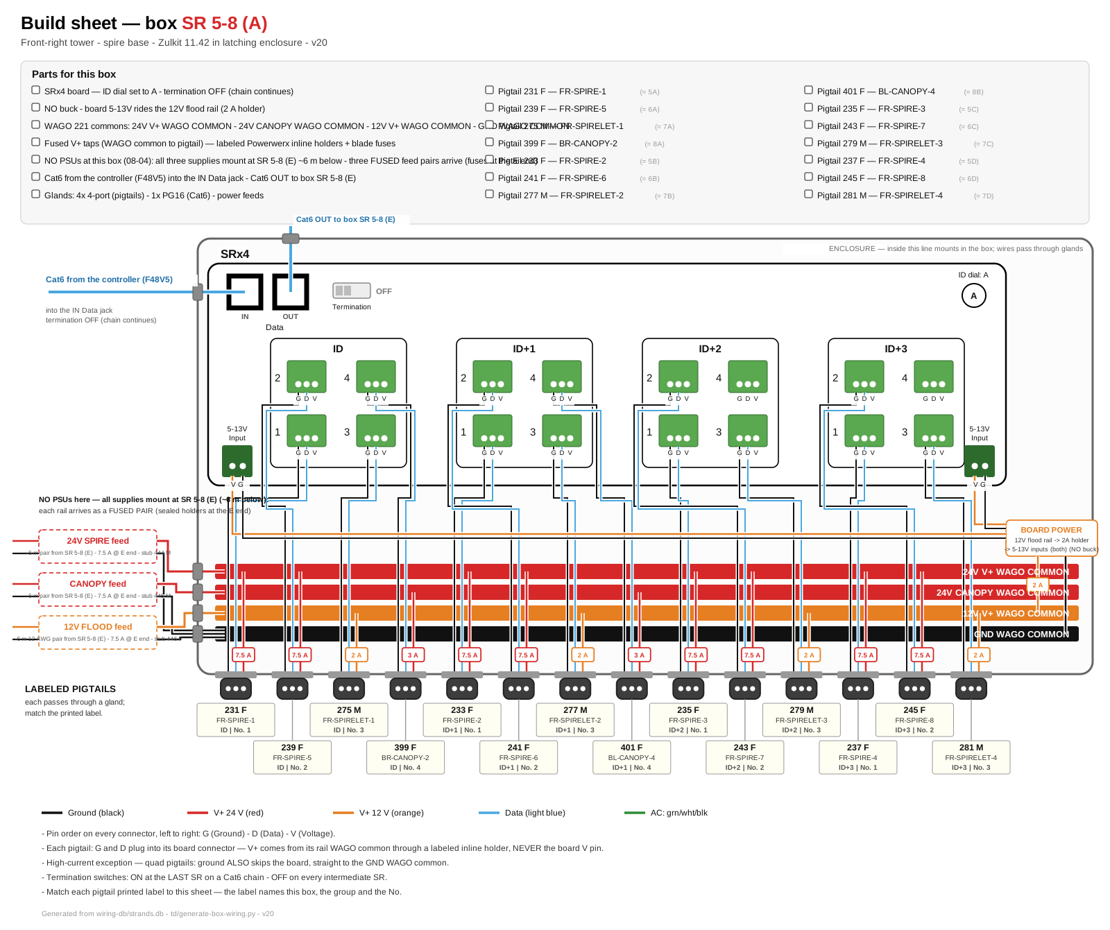
Click for full size. This is the printable installer sheet: parts checklist, board hookups, buses, fuses, and the labeled pigtails for this box.
Mounting assembly — plywood panel, PSUs, gland positions
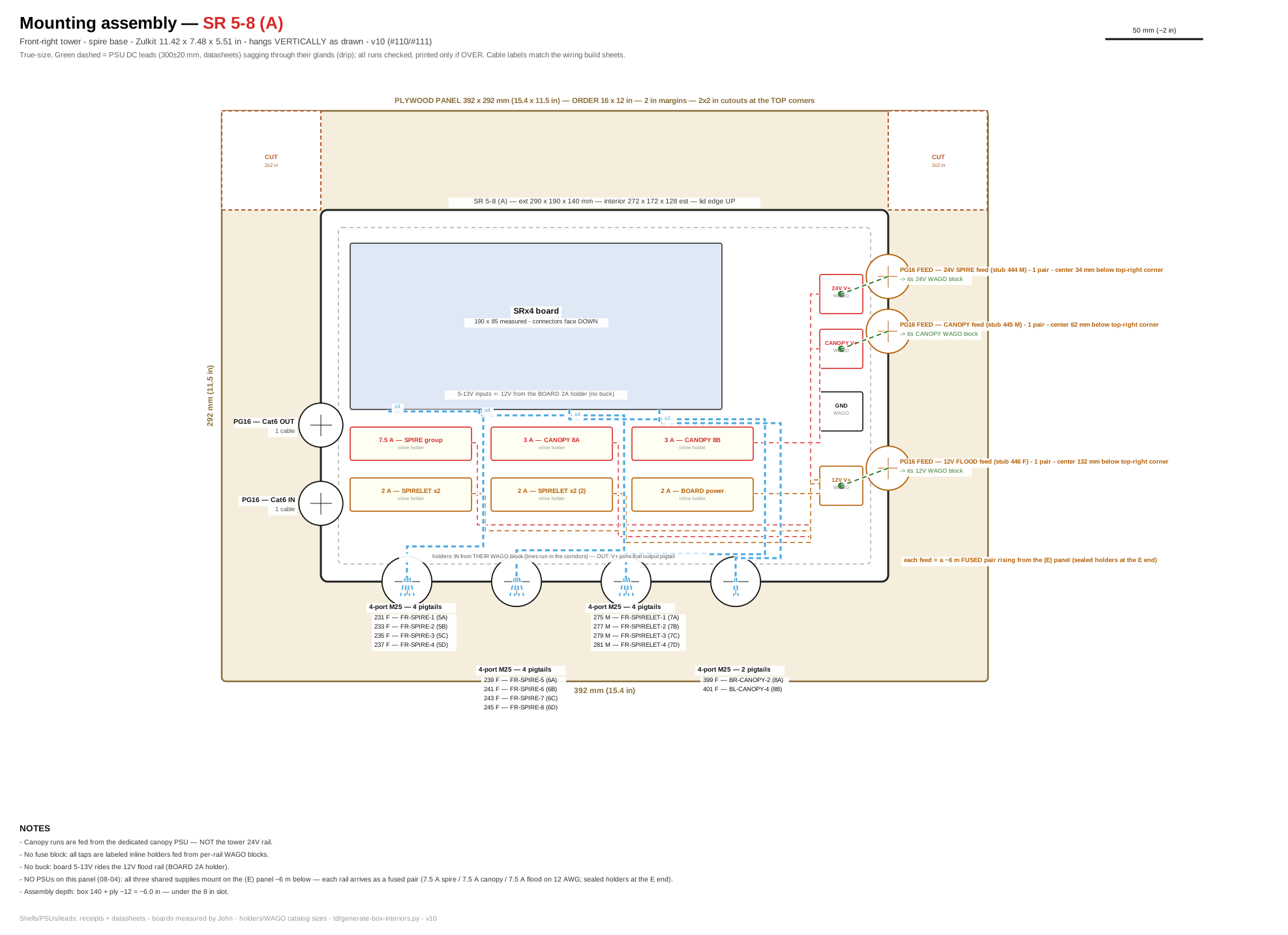
Click for full size. True-size layout of the plywood panel: enclosure placement, PSU positions, DC lead runs (green dashed = drip sag), gland walls with their cable lists, and the dashed CUT squares (2 in margins; 2×2 in top-corner cutouts; 0.5 m side notches on panels over 0.5 m — no cutouts on the major-arch panel). Panel size for every box: plywood cut list.
Sockets — what plugs in. Match the Cable label to the printed tag on each cable.
| Socket on board | Cable label | What it lights | Port | Data (tech) |
|---|---|---|---|---|
| Row ID · No.1 | 231 F FR-SPIRE-1 | Spire strand 1 — back-most strand | 5A | u50 ch1 · 13 px |
| Row ID · No.2 | 239 F FR-SPIRE-5 | Spire strand 5 | 6A | u53 ch1 · 13 px |
| Row ID · No.3 | 275 M FR-SPIRELET-1 | Spirelet FR-1 (upper, front, right) | 7A | u54 ch1 · 1 px |
| Row ID · No.4 | 399 F BR-CANOPY-2 | Canopy: BR → FR tower, rising (44 globes) — front-fed #95 | 8A | u55 ch1 · 44 px |
| Row ID+1 · No.1 | 233 F FR-SPIRE-2 | Spire strand 2 | 5B | u50 ch40 · 13 px |
| Row ID+1 · No.2 | 241 F FR-SPIRE-6 | Spire strand 6 | 6B | u53 ch40 · 13 px |
| Row ID+1 · No.3 | 277 M FR-SPIRELET-2 | Spirelet FR-2 (upper, front, left) | 7B | u54 ch4 · 1 px |
| Row ID+1 · No.4 | 401 F BL-CANOPY-4 | Canopy: BL → FR tower, diagonal (44 globes) — front-fed #95 | 8B | u55 ch133 · 44 px |
| Row ID+2 · No.1 | 235 F FR-SPIRE-3 | Spire strand 3 | 5C | u50 ch79 · 13 px |
| Row ID+2 · No.2 | 243 F FR-SPIRE-7 | Spire strand 7 | 6C | u53 ch79 · 13 px |
| Row ID+2 · No.3 | 279 M FR-SPIRELET-3 | Spirelet FR-3 (upper, back, left) | 7C | u54 ch7 · 1 px |
| Row ID+2 · No.4 | — | intentionally empty | 8C | — |
| Row ID+3 · No.1 | 237 F FR-SPIRE-4 | Spire strand 4 | 5D | u50 ch118 · 13 px |
| Row ID+3 · No.2 | 245 F FR-SPIRE-8 | Spire strand 8 | 6D | u53 ch118 · 13 px |
| Row ID+3 · No.3 | 281 M FR-SPIRELET-4 | Spirelet FR-4 (upper, back, right) | 7D | u54 ch10 · 1 px |
| Row ID+3 · No.4 | — | intentionally empty | 8D | — |
SR 5-8 (E) — Front-Right Tower
Where: low corner — back-right corner of the quad arch
What this box does: Drives the whole front-top-right quad arch as ONE chained string, plus the 2 lower spirelets, the 7-flood wash chain (8E, #99), and the lower canopy run. Wash chain order: starts at the INNER-FRONT corner (rose-window side) — the stacked bracket’s UP flood is pixel 1, DOWN flood pixel 2 — then counter-clockwise around the outside: front → right → back faces. See the Wash Floods reference.
| Board inside | Falcon SRx2 — ID dial set to E |
| Network in | Cat6 chained from SR 5-8 (A). Same 4 ports; this box answers as dials E and F. |
| Board power | 12 V board power from the tower 12 V flood rail (2 A BOARD holder — no buck). Quad LED power comes from the fused 24 V WAGO tap — NOT this board. HOSTS all three tower supplies (08-04): PSU-S 24 V + PSU-Y canopy + the 12 V flood PSU all mount on THIS panel; three fused feed pairs run ~6 m up to SR 5-8 (A). |
| Fusing | Quad: two 15 A taps (12 AWG) — at this corner and the opposite corner. Lower canopy run 3 A from the dedicated canopy PSU (PSU-Y), not the tower rail. Lower spirelets on the 12 V flood PSU, 2 A group; wash chain on the same 12 V flood PSU, one 7.5 A tap (7 floods ≈ 5.8 A full white). |
Internal wiring — build sheet
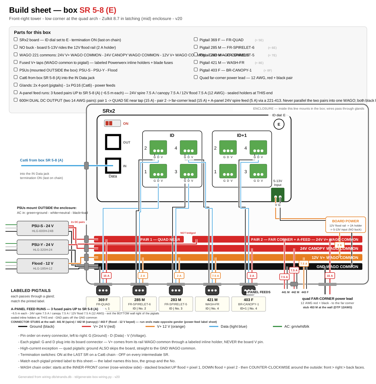
Click for full size. This is the printable installer sheet: parts checklist, board hookups, buses, fuses, and the labeled pigtails for this box.
Mounting assembly — plywood panel, PSUs, gland positions

Click for full size. True-size layout of the plywood panel: enclosure placement, PSU positions, DC lead runs (green dashed = drip sag), gland walls with their cable lists, and the dashed CUT squares (2 in margins; 2×2 in top-corner cutouts; 0.5 m side notches on panels over 0.5 m — no cutouts on the major-arch panel). Panel size for every box: plywood cut list.
Sockets — what plugs in. Match the Cable label to the printed tag on each cable.
| Socket on board | Cable label | What it lights | Port | Data (tech) |
|---|---|---|---|---|
| Row ID · No.1 | 369 F FR-QUAD | CHAINED QUAD front-top-right — 4 faces F→L→B→R, px 0 = front-right foot | 5E | u50 ch157 · 340 px |
| Row ID · No.2 | 285 M FR-SPIRELET-6 | Spirelet FR-6 (lower, front, right) | 6E | u53 ch157 · 1 px |
| Row ID · No.3 | 283 M FR-SPIRELET-5 | Spirelet FR-5 (lower, back, right) | 7E | u54 ch13 · 1 px |
| Row ID · No.4 | 421 M WASH-FR | WASH x7 chained front-right — chain starts at the inner-front corner (rose-window side): stacked pair UP flood then DOWN flood, then COUNTER-CLOCKWISE around the outside (front, right, back faces) — data from low SRx2, V+ from 12 V flood rail (#99) | 8E | u55 ch379 · 7 px |
| Row ID+1 · No.1 | — | intentionally empty | 5F | — |
| Row ID+1 · No.2 | — | intentionally empty | 6F | — |
| Row ID+1 · No.3 | — | intentionally empty | 7F | — |
| Row ID+1 · No.4 | 403 F BR-CANOPY-1 | Canopy: BR → FR tower, straight across (38 globes) — lower, front-fed #95 | 8F | u55 ch265 · 38 px |
SR 9-12 (A) — Front-Left Tower
Where: spire base (top of tower)
What this box does: Lights the front-left spire (8 globe strings), 4 upper spirelets, and 2 of the 3 canopy runs that land on this tower.
| Board inside | Falcon SRx4 — ID dial set to A |
| Network in | One Cat6 from the controller (ports 9–12), routed up the front-right tower and across the support wire between the front towers. Chains on to SR 9-12 (E). |
| Board power | 12 V board power from the tower 12 V flood rail (2 A BOARD holder — no buck). LED power NEVER flows through this box. NO PSUs at this panel (08-04): all three tower supplies mount at SR 9-12 (E) ~6 m below — each rail arrives as a fused pair (7.5 A spire / 7.5 A canopy / 7.5 A flood on 12 AWG; sealed holders at the E end). |
| Fusing | Spire strings 7.5 A group. Canopy V+ from the dedicated canopy PSU (PSU-Z), 3 A per run — NOT the tower 24 V rail. Spirelets on the tower 12 V flood PSU, 2 A group. |
Internal wiring — build sheet
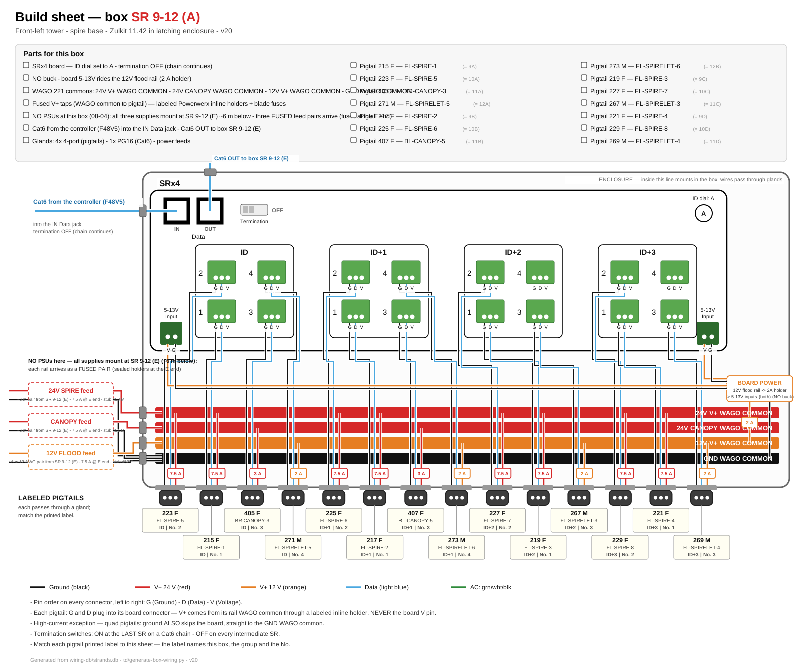
Click for full size. This is the printable installer sheet: parts checklist, board hookups, buses, fuses, and the labeled pigtails for this box.
Mounting assembly — plywood panel, PSUs, gland positions
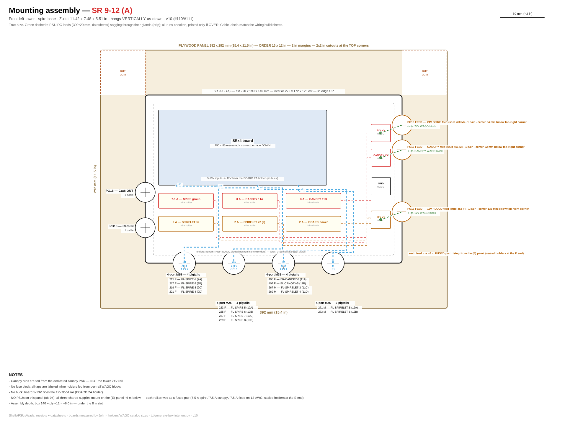
Click for full size. True-size layout of the plywood panel: enclosure placement, PSU positions, DC lead runs (green dashed = drip sag), gland walls with their cable lists, and the dashed CUT squares (2 in margins; 2×2 in top-corner cutouts; 0.5 m side notches on panels over 0.5 m — no cutouts on the major-arch panel). Panel size for every box: plywood cut list.
Sockets — what plugs in. Match the Cable label to the printed tag on each cable.
| Socket on board | Cable label | What it lights | Port | Data (tech) |
|---|---|---|---|---|
| Row ID · No.1 | 215 F FL-SPIRE-1 | Spire strand 1 — back-most strand | 9A | u56 ch1 · 13 px |
| Row ID · No.2 | 223 F FL-SPIRE-5 | Spire strand 5 | 10A | u59 ch1 · 13 px |
| Row ID · No.3 | 405 F BR-CANOPY-3 | Canopy: BR → FL tower, diagonal (44 globes) — front-fed #95 | 11A | u60 ch10 · 44 px |
| Row ID · No.4 | 271 M FL-SPIRELET-5 | Spirelet FL-5 (upper, front, right) | 12A | u61 ch1 · 1 px |
| Row ID+1 · No.1 | 217 F FL-SPIRE-2 | Spire strand 2 | 9B | u56 ch40 · 13 px |
| Row ID+1 · No.2 | 225 F FL-SPIRE-6 | Spire strand 6 | 10B | u59 ch40 · 13 px |
| Row ID+1 · No.3 | 407 F BL-CANOPY-5 | Canopy: BL → FL tower, rising (44 globes) — front-fed #95 | 11B | u60 ch142 · 44 px |
| Row ID+1 · No.4 | 273 M FL-SPIRELET-6 | Spirelet FL-6 (upper, front, left) | 12B | u61 ch4 · 1 px |
| Row ID+2 · No.1 | 219 F FL-SPIRE-3 | Spire strand 3 | 9C | u56 ch79 · 13 px |
| Row ID+2 · No.2 | 227 F FL-SPIRE-7 | Spire strand 7 | 10C | u59 ch79 · 13 px |
| Row ID+2 · No.3 | 267 M FL-SPIRELET-3 | Spirelet FL-3 (upper, back, left) | 11C | u60 ch1 · 1 px |
| Row ID+2 · No.4 | — | intentionally empty | 12C | — |
| Row ID+3 · No.1 | 221 F FL-SPIRE-4 | Spire strand 4 | 9D | u56 ch118 · 13 px |
| Row ID+3 · No.2 | 229 F FL-SPIRE-8 | Spire strand 8 | 10D | u59 ch118 · 13 px |
| Row ID+3 · No.3 | 269 M FL-SPIRELET-4 | Spirelet FL-4 (upper, back, right) | 11D | u60 ch4 · 1 px |
| Row ID+3 · No.4 | — | intentionally empty | 12D | — |
SR 9-12 (E) — Front-Left Tower
Where: low corner — back-left corner of the quad arch
What this box does: Drives the whole front-top-left quad arch as ONE chained string, plus the 2 lower spirelets, the 7-flood wash chain (12E, #99), and the lower canopy run. Wash chain order: starts at the INNER-FRONT corner (rose-window side) — the stacked bracket’s UP flood is pixel 1, DOWN flood pixel 2 — then clockwise around the outside: front → left → back faces. See the Wash Floods reference.
| Board inside | Falcon SRx2 — ID dial set to E |
| Network in | Cat6 chained from SR 9-12 (A). Answers as dials E and F. |
| Board power | 12 V board power from the tower 12 V flood rail (2 A BOARD holder — no buck). HOSTS all three tower supplies (08-04): PSU-T 24 V + PSU-Z canopy + the 12 V flood PSU all mount on THIS panel; three fused feed pairs run ~6 m up to SR 9-12 (A). |
| Fusing | Quad: two 15 A taps (this corner + opposite). Lower canopy run 3 A from the dedicated canopy PSU (PSU-Z), not the tower rail. Lower spirelets on the 12 V flood PSU, 2 A group; wash chain on the same 12 V flood PSU, one 7.5 A tap (7 floods ≈ 5.8 A full white). |
Internal wiring — build sheet
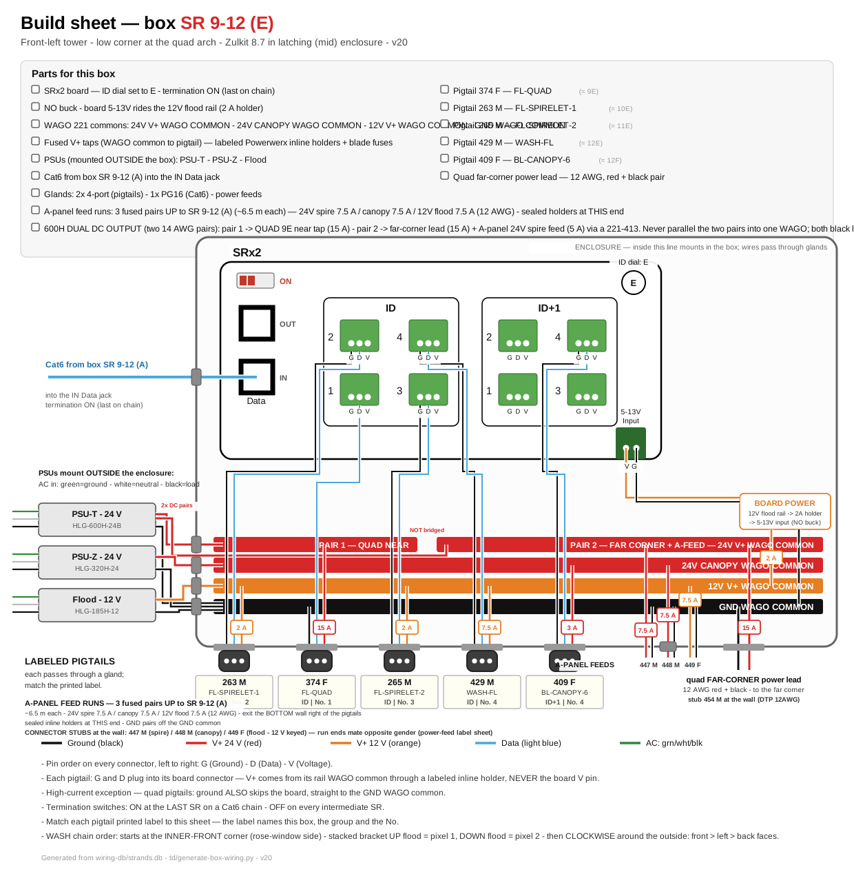
Click for full size. This is the printable installer sheet: parts checklist, board hookups, buses, fuses, and the labeled pigtails for this box.
Mounting assembly — plywood panel, PSUs, gland positions
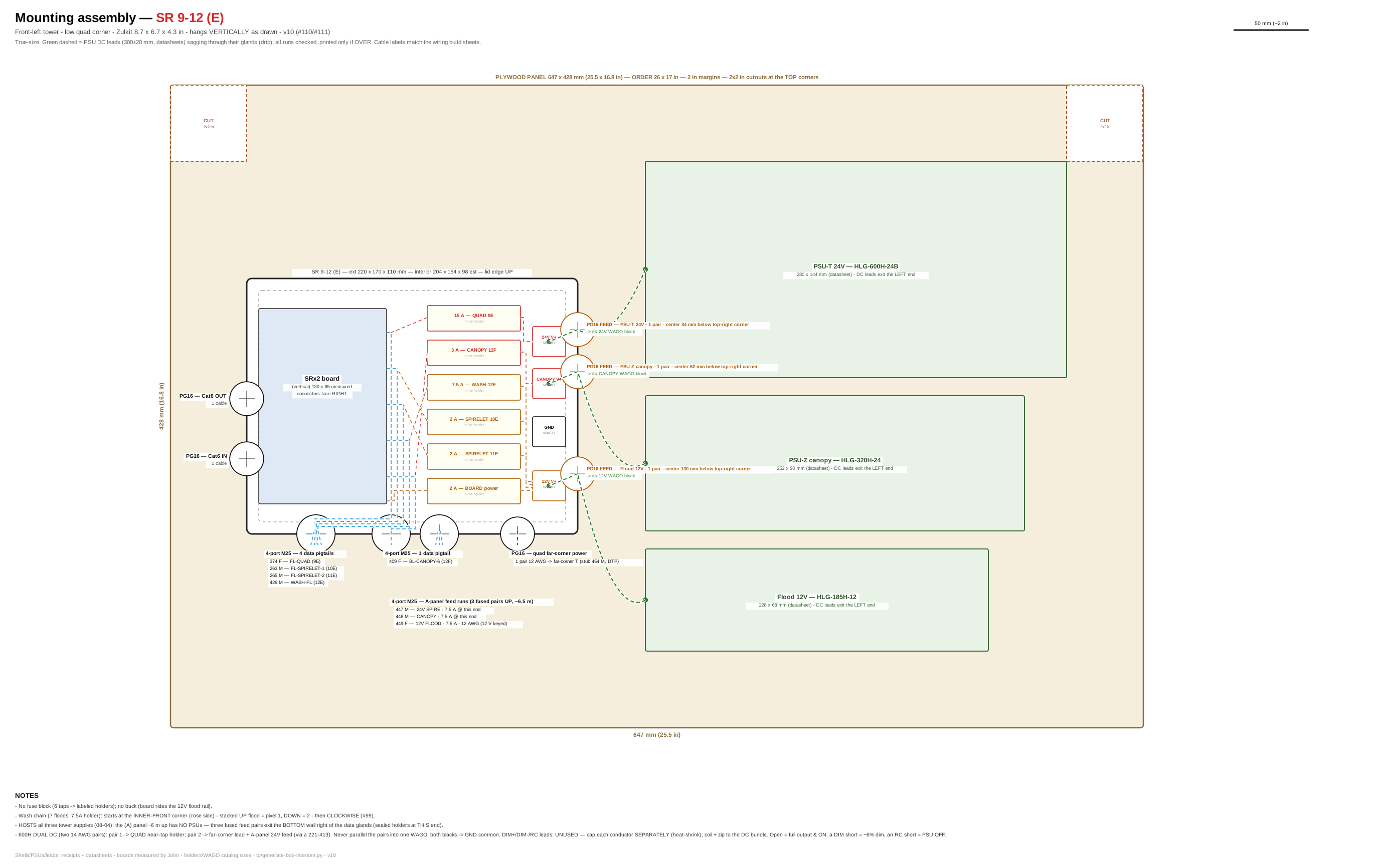
Click for full size. True-size layout of the plywood panel: enclosure placement, PSU positions, DC lead runs (green dashed = drip sag), gland walls with their cable lists, and the dashed CUT squares (2 in margins; 2×2 in top-corner cutouts; 0.5 m side notches on panels over 0.5 m — no cutouts on the major-arch panel). Panel size for every box: plywood cut list.
Sockets — what plugs in. Match the Cable label to the printed tag on each cable.
| Socket on board | Cable label | What it lights | Port | Data (tech) |
|---|---|---|---|---|
| Row ID · No.1 | 374 F FL-QUAD | CHAINED QUAD front-top-left — 4 faces F→L→B→R, px 0 = front-right foot | 9E | u56 ch157 · 340 px |
| Row ID · No.2 | 263 M FL-SPIRELET-1 | Spirelet FL-1 (lower, front, left) | 10E | u59 ch157 · 1 px |
| Row ID · No.3 | 265 M FL-SPIRELET-2 | Spirelet FL-2 (lower, back, left) | 11E | u60 ch7 · 1 px |
| Row ID · No.4 | 429 M WASH-FL | WASH x7 chained front-left — chain starts at the inner-front corner (rose-window side): stacked pair UP flood then DOWN flood, then CLOCKWISE around the outside (front, left, back faces) — data from low SRx2, V+ from 12 V flood rail (#99) | 12E | u61 ch121 · 7 px |
| Row ID+1 · No.1 | — | intentionally empty | 9F | — |
| Row ID+1 · No.2 | — | intentionally empty | 10F | — |
| Row ID+1 · No.3 | — | intentionally empty | 11F | — |
| Row ID+1 · No.4 | 409 F BL-CANOPY-6 | Canopy: BL → FL tower, straight across (38 globes) — lower, front-fed #95 | 12F | u61 ch7 · 38 px |
SR 13-16 (A) — Back-Left Tower
Where: spire base (top of tower)
What this box does: Lights the back-left spire (8 globe strings), its 4 spirelets, the back-top-left quad arch (one chained string on its spare socket), and the 4-flood wash chain around the top quad (16A, #102). Wash chain order: data feeds the FRONT-face flood first, then clockwise — Front → Left → Back → Right (pixel 1 = front). See the Wash Floods reference.
| Board inside | Falcon SRx4 — ID dial set to A |
| Network in | One Cat6 from the controller (ports 13–16), routed along the diagonal canopy line from the front-right tower. Chains on to SR 13-16 (E). |
| Board power | 12 V board power from the tower 12 V flood rail (2 A BOARD holder — no buck). |
| Fusing | Spire strings 7.5 A group; quad-top: 15 A tap at the SR corner (single-end feed — add opposite tap only if far globes dim). Spirelets on the tower 12 V flood PSU, 2 A group; wash chain on the same 12 V flood PSU, one 5 A tap. |
Internal wiring — build sheet
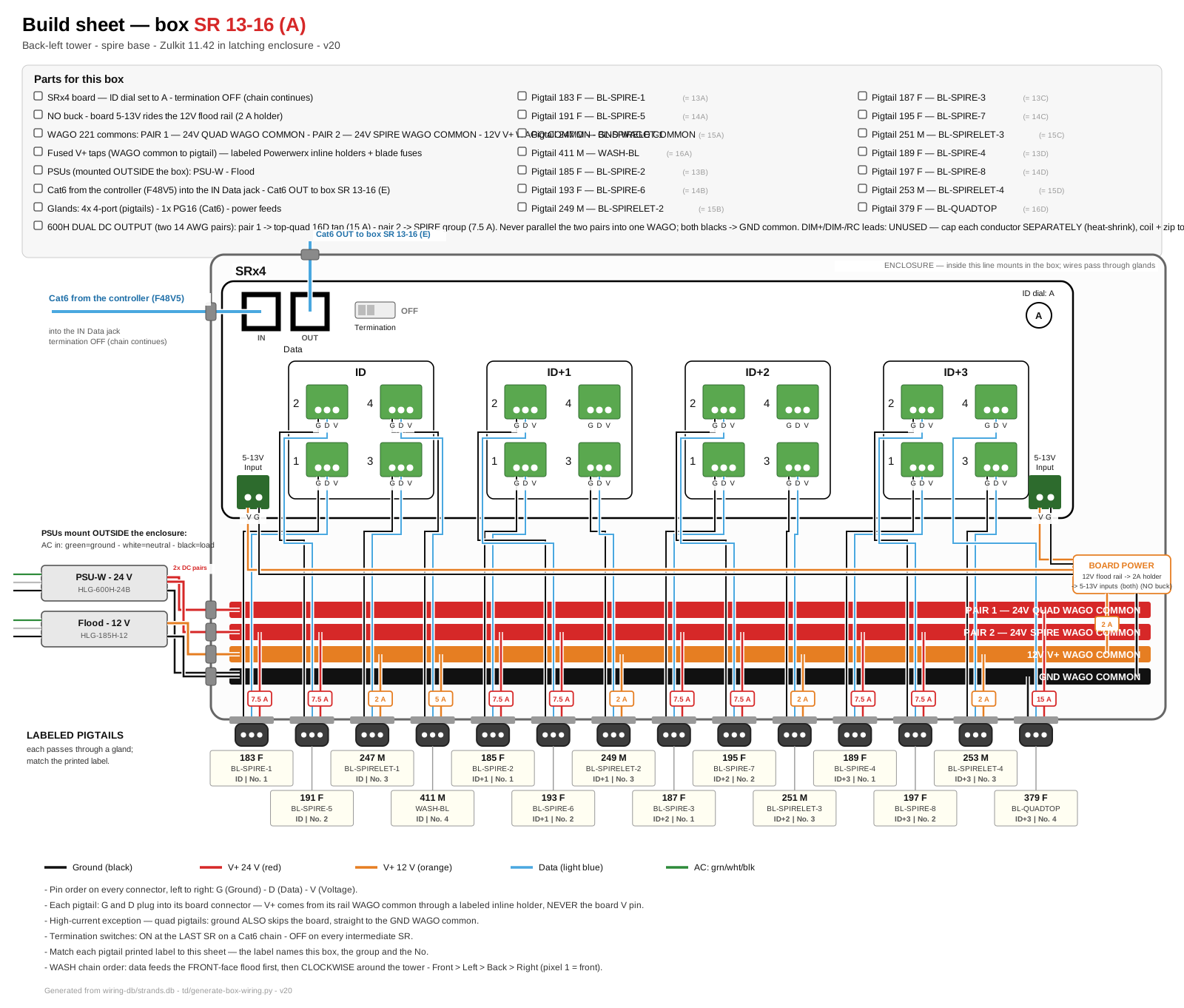
Click for full size. This is the printable installer sheet: parts checklist, board hookups, buses, fuses, and the labeled pigtails for this box.
Mounting assembly — plywood panel, PSUs, gland positions
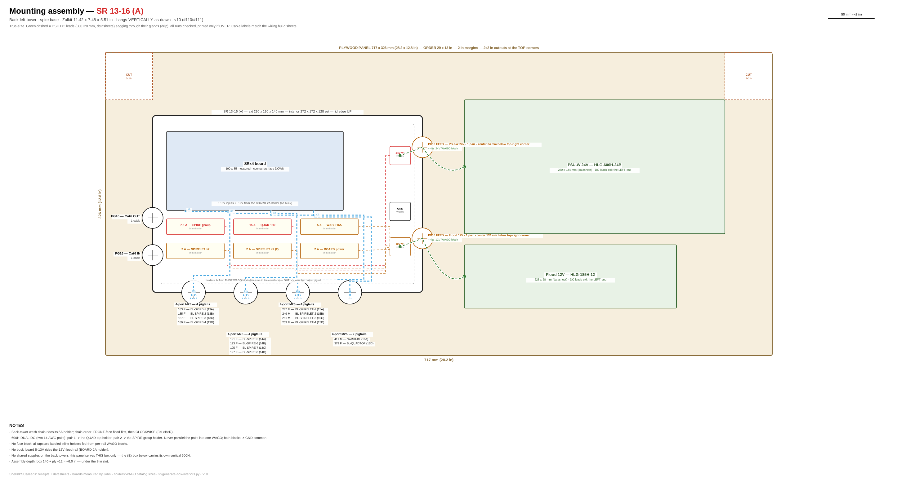
Click for full size. True-size layout of the plywood panel: enclosure placement, PSU positions, DC lead runs (green dashed = drip sag), gland walls with their cable lists, and the dashed CUT squares (2 in margins; 2×2 in top-corner cutouts; 0.5 m side notches on panels over 0.5 m — no cutouts on the major-arch panel). Panel size for every box: plywood cut list.
Sockets — what plugs in. Match the Cable label to the printed tag on each cable.
| Socket on board | Cable label | What it lights | Port | Data (tech) |
|---|---|---|---|---|
| Row ID · No.1 | 183 F BL-SPIRE-1 | Spire strand 1 — back-most strand | 13A | u62 ch1 · 13 px |
| Row ID · No.2 | 191 F BL-SPIRE-5 | Spire strand 5 | 14A | u65 ch1 · 13 px |
| Row ID · No.3 | 247 M BL-SPIRELET-1 | Spirelet BL-1 (front, left) | 15A | u66 ch1 · 1 px |
| Row ID · No.4 | 411 M WASH-BL | WASH x4 chained back-left — one flood mid-face on each face of the top quad (F, L, B, R), one feed — data from SR, V+ from 12 V flood rail (#102) | 16A | u67 ch1 · 4 px |
| Row ID+1 · No.1 | 185 F BL-SPIRE-2 | Spire strand 2 | 13B | u62 ch40 · 13 px |
| Row ID+1 · No.2 | 193 F BL-SPIRE-6 | Spire strand 6 | 14B | u65 ch40 · 13 px |
| Row ID+1 · No.3 | 249 M BL-SPIRELET-2 | Spirelet BL-2 (back, left) | 15B | u66 ch4 · 1 px |
| Row ID+1 · No.4 | — | intentionally empty — canopy moved to front towers (#95) | 16B | — |
| Row ID+2 · No.1 | 187 F BL-SPIRE-3 | Spire strand 3 | 13C | u62 ch79 · 13 px |
| Row ID+2 · No.2 | 195 F BL-SPIRE-7 | Spire strand 7 | 14C | u65 ch79 · 13 px |
| Row ID+2 · No.3 | 251 M BL-SPIRELET-3 | Spirelet BL-3 (back, right) | 15C | u66 ch7 · 1 px |
| Row ID+2 · No.4 | — | intentionally empty — canopy moved to front towers (#95) | 16C | — |
| Row ID+3 · No.1 | 189 F BL-SPIRE-4 | Spire strand 4 | 13D | u62 ch118 · 13 px |
| Row ID+3 · No.2 | 197 F BL-SPIRE-8 | Spire strand 8 | 14D | u65 ch118 · 13 px |
| Row ID+3 · No.3 | 253 M BL-SPIRELET-4 | Spirelet BL-4 (front, right) | 15D | u66 ch10 · 1 px |
| Row ID+3 · No.4 | 379 F BL-QUADTOP | CHAINED QUAD back-top-left — 4 faces F→L→B→R | 16D | u67 ch379 · 176 px |
SR 13-16 (E) — Back-Left Tower
Where: back-left corner of the back-bottom quad arch
What this box does: Drives the whole back-bottom-left quad arch as ONE chained string. The other three sockets are intentionally empty.
| Board inside | Falcon SRx1 — ID dial set to E |
| Network in | Cat6 chained from SR 13-16 (A). Answers as dial E. |
| Board power | 12 V board power from the 10 A buck (24 V WAGO common → buck → board 5-13V input). |
| Fusing | Quad: two 15 A taps (this corner + opposite corner). |
Internal wiring — build sheet
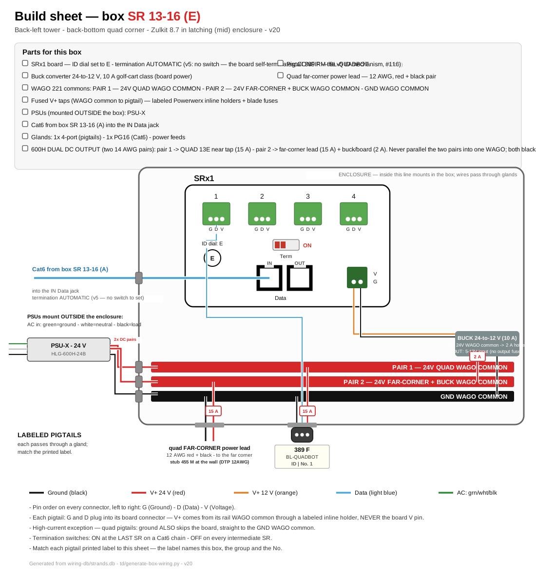
Click for full size. This is the printable installer sheet: parts checklist, board hookups, buses, fuses, and the labeled pigtails for this box.
Mounting assembly — plywood panel, PSUs, gland positions
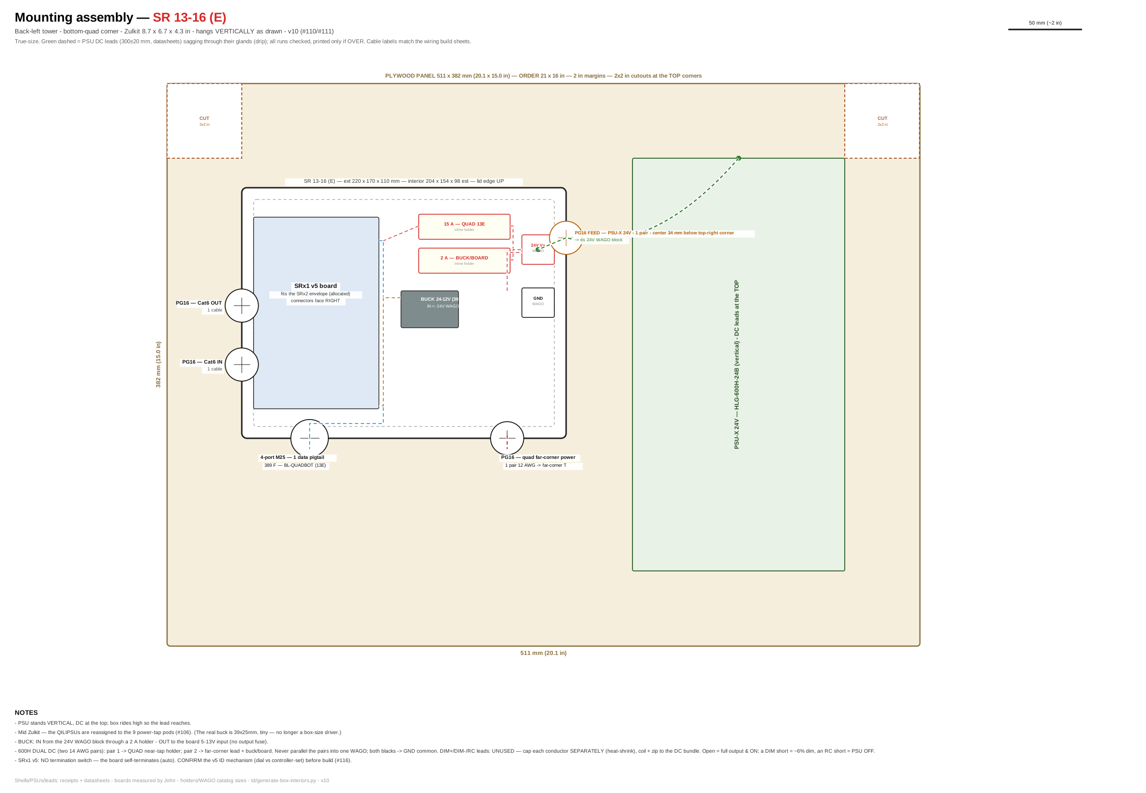
Click for full size. True-size layout of the plywood panel: enclosure placement, PSU positions, DC lead runs (green dashed = drip sag), gland walls with their cable lists, and the dashed CUT squares (2 in margins; 2×2 in top-corner cutouts; 0.5 m side notches on panels over 0.5 m — no cutouts on the major-arch panel). Panel size for every box: plywood cut list.
Sockets — what plugs in. Match the Cable label to the printed tag on each cable.
| Socket on board | Cable label | What it lights | Port | Data (tech) |
|---|---|---|---|---|
| No.1 | 389 F BL-QUADBOT | CHAINED QUAD back-bottom-left — 4 faces F→L→B→R | 13E | u62 ch157 · 332 px |
| No.2 | — | intentionally empty | 14E | — |
| No.3 | — | intentionally empty | 15E | — |
| No.4 | — | intentionally empty | 16E | — |
SR 17-20 (A) — Back-Right Tower
Where: spire base (top of tower)
What this box does: Mirror of the back-left box: back-right spire (8 strings), 4 spirelets, the back-top-right quad arch on its spare socket, and the 4-flood wash chain around the top quad (20A, #102). Wash chain order: data feeds the FRONT-face flood first, then clockwise — Front → Left → Back → Right (pixel 1 = front). See the Wash Floods reference.
| Board inside | Falcon SRx4 — ID dial set to A |
| Network in | One Cat6 from the controller (ports 17–20), routed along the rightmost canopy line straight back. Chains on to SR 17-20 (E). |
| Board power | 12 V board power from the tower 12 V flood rail (2 A BOARD holder — no buck). |
| Fusing | Spire strings 7.5 A group; quad-top 15 A tap at SR corner (single-end). Spirelets on the tower 12 V flood PSU, 2 A group; wash chain on the same 12 V flood PSU, one 5 A tap. |
Internal wiring — build sheet
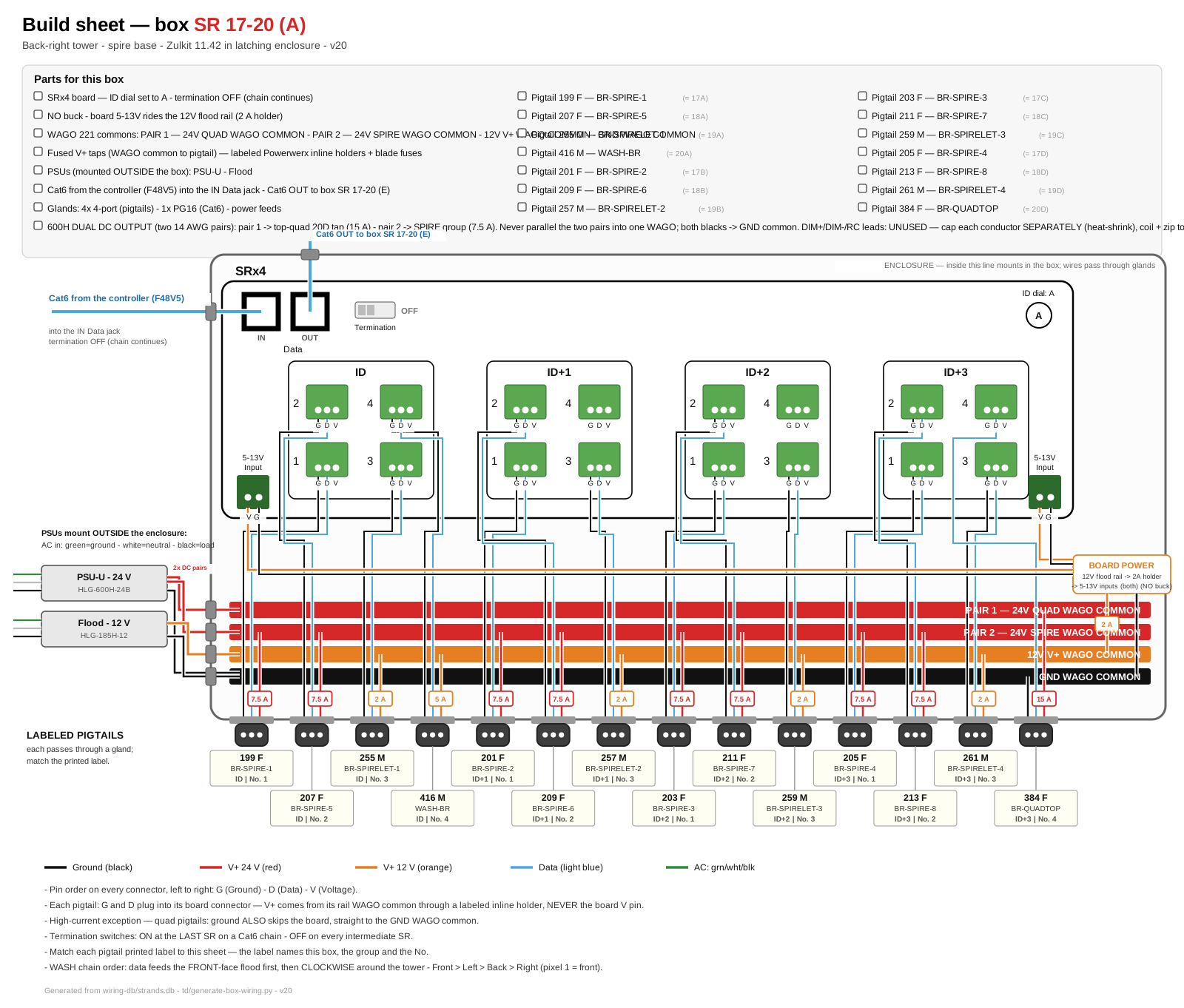
Click for full size. This is the printable installer sheet: parts checklist, board hookups, buses, fuses, and the labeled pigtails for this box.
Mounting assembly — plywood panel, PSUs, gland positions
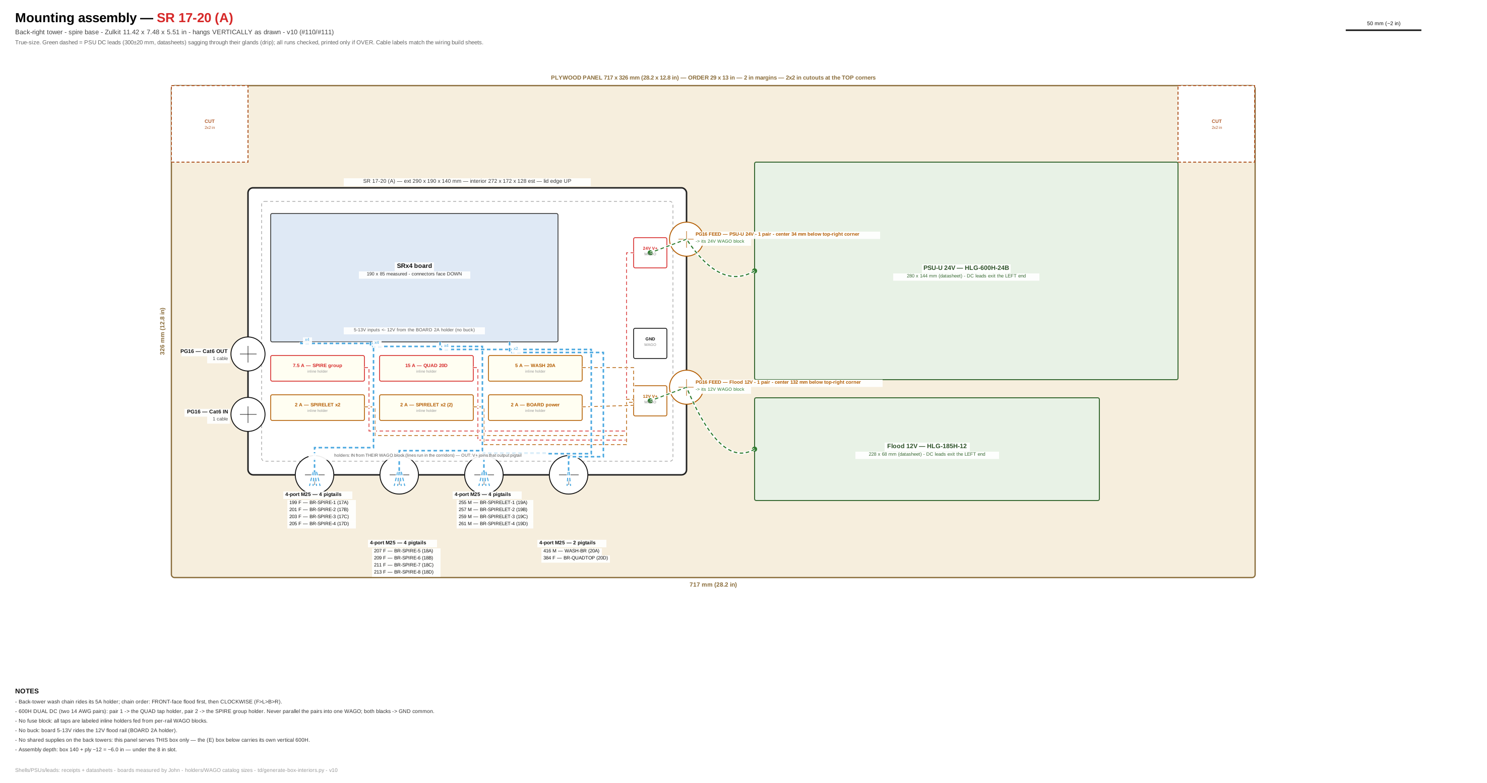
Click for full size. True-size layout of the plywood panel: enclosure placement, PSU positions, DC lead runs (green dashed = drip sag), gland walls with their cable lists, and the dashed CUT squares (2 in margins; 2×2 in top-corner cutouts; 0.5 m side notches on panels over 0.5 m — no cutouts on the major-arch panel). Panel size for every box: plywood cut list.
Sockets — what plugs in. Match the Cable label to the printed tag on each cable.
| Socket on board | Cable label | What it lights | Port | Data (tech) |
|---|---|---|---|---|
| Row ID · No.1 | 199 F BR-SPIRE-1 | Spire strand 1 — back-most strand | 17A | u69 ch1 · 13 px |
| Row ID · No.2 | 207 F BR-SPIRE-5 | Spire strand 5 | 18A | u72 ch1 · 13 px |
| Row ID · No.3 | 255 M BR-SPIRELET-1 | Spirelet BR-1 (front, left) | 19A | u73 ch1 · 1 px |
| Row ID · No.4 | 416 M WASH-BR | WASH x4 chained back-right — one flood mid-face on each face of the top quad (F, L, B, R), one feed — data from SR, V+ from 12 V flood rail (#102) | 20A | u74 ch1 · 4 px |
| Row ID+1 · No.1 | 201 F BR-SPIRE-2 | Spire strand 2 | 17B | u69 ch40 · 13 px |
| Row ID+1 · No.2 | 209 F BR-SPIRE-6 | Spire strand 6 | 18B | u72 ch40 · 13 px |
| Row ID+1 · No.3 | 257 M BR-SPIRELET-2 | Spirelet BR-2 (back, left) | 19B | u73 ch4 · 1 px |
| Row ID+1 · No.4 | — | intentionally empty — canopy moved to front towers (#95) | 20B | — |
| Row ID+2 · No.1 | 203 F BR-SPIRE-3 | Spire strand 3 | 17C | u69 ch79 · 13 px |
| Row ID+2 · No.2 | 211 F BR-SPIRE-7 | Spire strand 7 | 18C | u72 ch79 · 13 px |
| Row ID+2 · No.3 | 259 M BR-SPIRELET-3 | Spirelet BR-3 (back, right) | 19C | u73 ch7 · 1 px |
| Row ID+2 · No.4 | — | intentionally empty — canopy moved to front towers (#95) | 20C | — |
| Row ID+3 · No.1 | 205 F BR-SPIRE-4 | Spire strand 4 | 17D | u69 ch118 · 13 px |
| Row ID+3 · No.2 | 213 F BR-SPIRE-8 | Spire strand 8 | 18D | u72 ch118 · 13 px |
| Row ID+3 · No.3 | 261 M BR-SPIRELET-4 | Spirelet BR-4 (front, right) | 19D | u73 ch10 · 1 px |
| Row ID+3 · No.4 | 384 F BR-QUADTOP | CHAINED QUAD back-top-right — 4 faces F→L→B→R | 20D | u74 ch379 · 176 px |
SR 17-20 (E) — Back-Right Tower
Where: back-left corner of the back-bottom quad arch
What this box does: Drives the whole back-bottom-right quad arch as ONE chained string. Other three sockets intentionally empty.
| Board inside | Falcon SRx1 — ID dial set to E |
| Network in | Cat6 chained from SR 17-20 (A). Answers as dial E. |
| Board power | 12 V board power from the 10 A buck (24 V WAGO common → buck → board 5-13V input). |
| Fusing | Quad: two 15 A taps (this corner + opposite corner). |
Internal wiring — build sheet
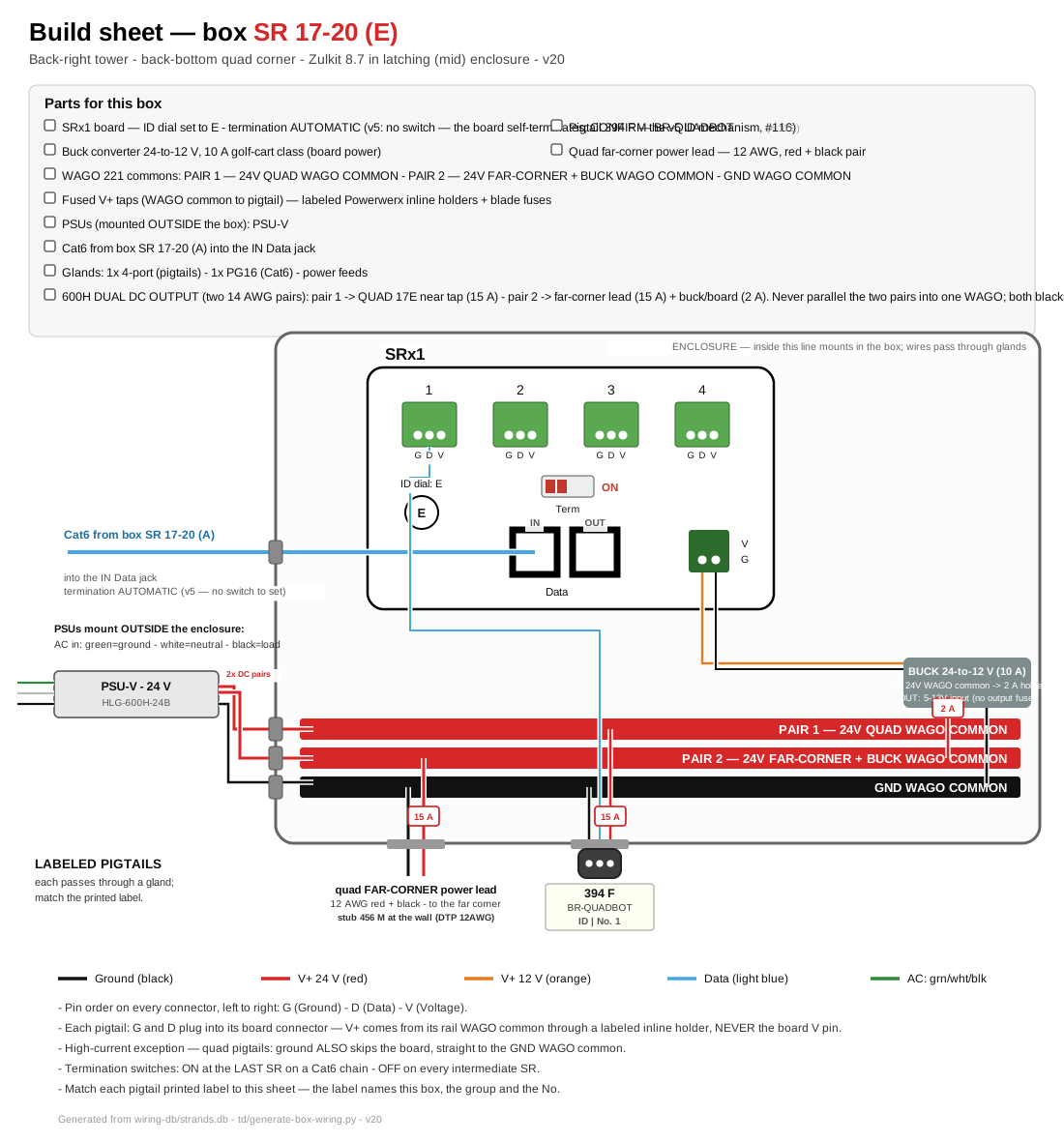
Click for full size. This is the printable installer sheet: parts checklist, board hookups, buses, fuses, and the labeled pigtails for this box.
Mounting assembly — plywood panel, PSUs, gland positions
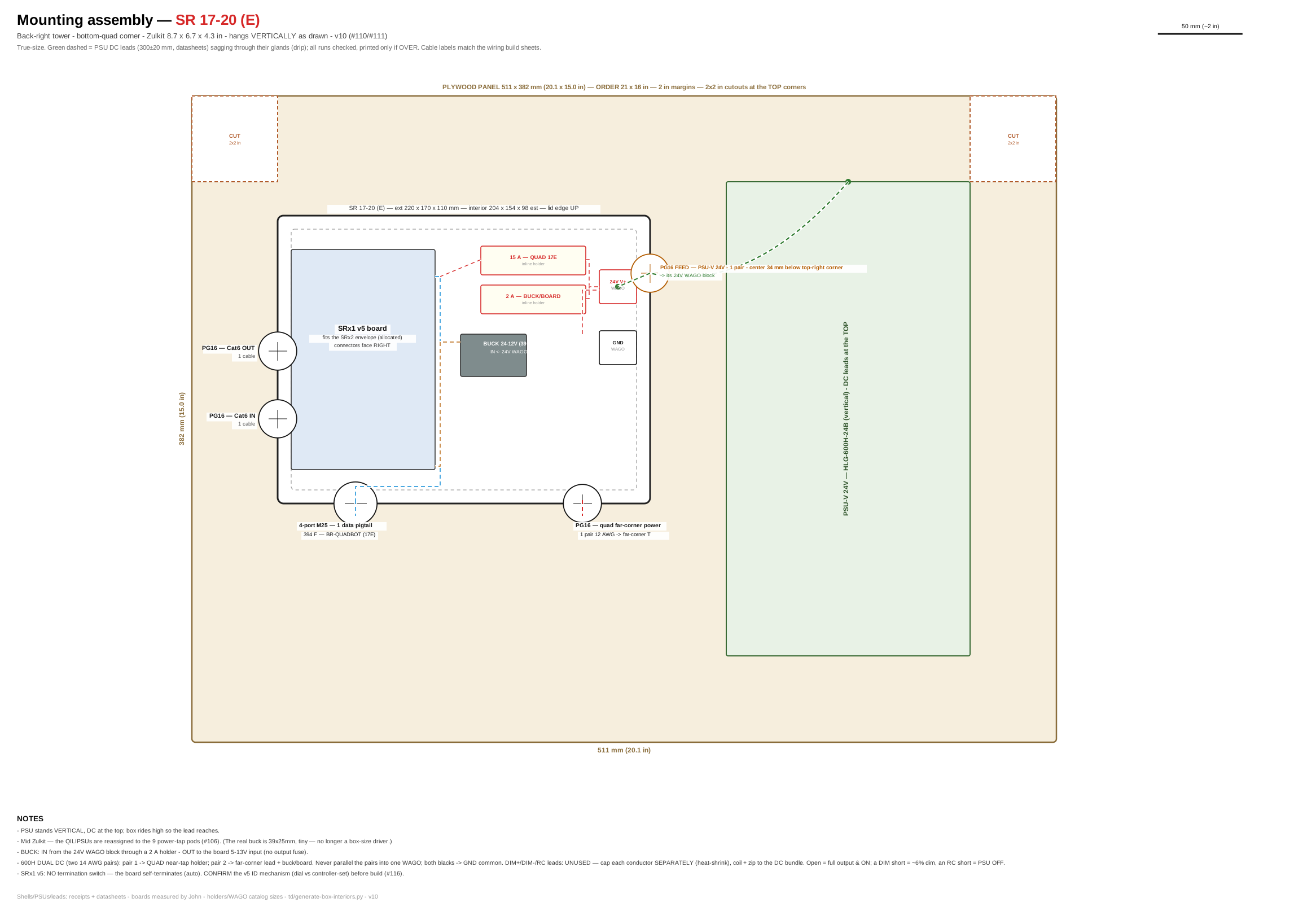
Click for full size. True-size layout of the plywood panel: enclosure placement, PSU positions, DC lead runs (green dashed = drip sag), gland walls with their cable lists, and the dashed CUT squares (2 in margins; 2×2 in top-corner cutouts; 0.5 m side notches on panels over 0.5 m — no cutouts on the major-arch panel). Panel size for every box: plywood cut list.
Sockets — what plugs in. Match the Cable label to the printed tag on each cable.
| Socket on board | Cable label | What it lights | Port | Data (tech) |
|---|---|---|---|---|
| No.1 | 394 F BR-QUADBOT | CHAINED QUAD back-bottom-right — 4 faces F→L→B→R | 17E | u69 ch157 · 332 px |
| No.2 | — | intentionally empty | 18E | — |
| No.3 | — | intentionally empty | 19E | — |
| No.4 | — | intentionally empty | 20E | — |
SR 21-24 (A) — Minor Arches — LEFT side
Where: inner foot of minor arch 3
What this box does: Lights all 5 minor arches on the LEFT side — one socket per arch, arch 5 on the second row. BOTH minor-arch PSUs (O + P) mount at this box; ALL arch power runs THROUGH the enclosure.
| Board inside | Falcon SRx2 — ID dial set to A |
| Network in | Cat6 from the controller: up the front-right tower, across the front support wire, down the front-left tower. Do NOT swap with the right-side Cat6. |
| Board power | PSU O feeds the ARCHES 1+2 bus, PSU P the ARCHES 3+4+5 bus — two isolated two isolated 24 V WAGO zones inside the box. Board runs on 12 V from the 10 A buck off the 3-5 zone. |
| Fusing | Every V+ line 5 A fused. 3 injection points per arch (data-in foot via the pigtail, peak T, far foot) — no V+ cut. SEPARATION RULE: arches 1-2 lines exit the LEFT wall of the box, arches 3-5 the RIGHT wall. Never mix buses. |
Internal wiring — build sheet
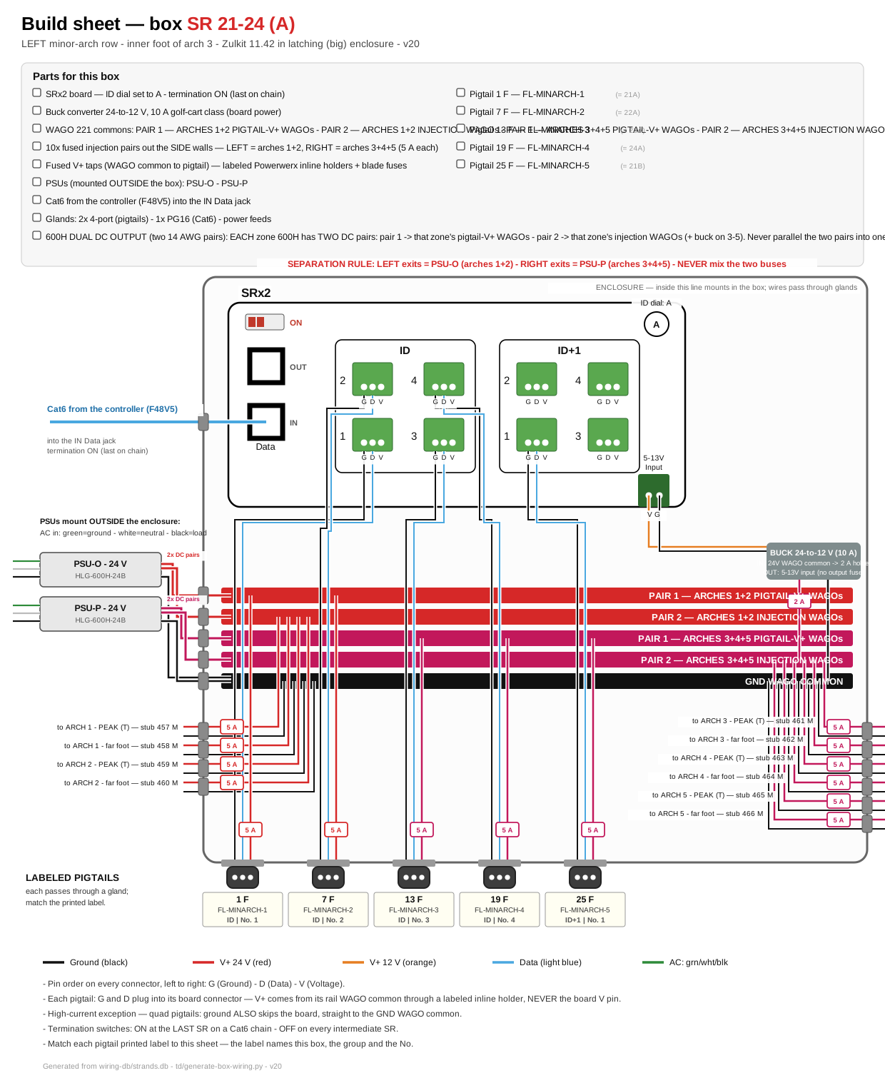
Click for full size. This is the printable installer sheet: parts checklist, board hookups, buses, fuses, and the labeled pigtails for this box.
Mounting assembly — plywood panel, PSUs, gland positions
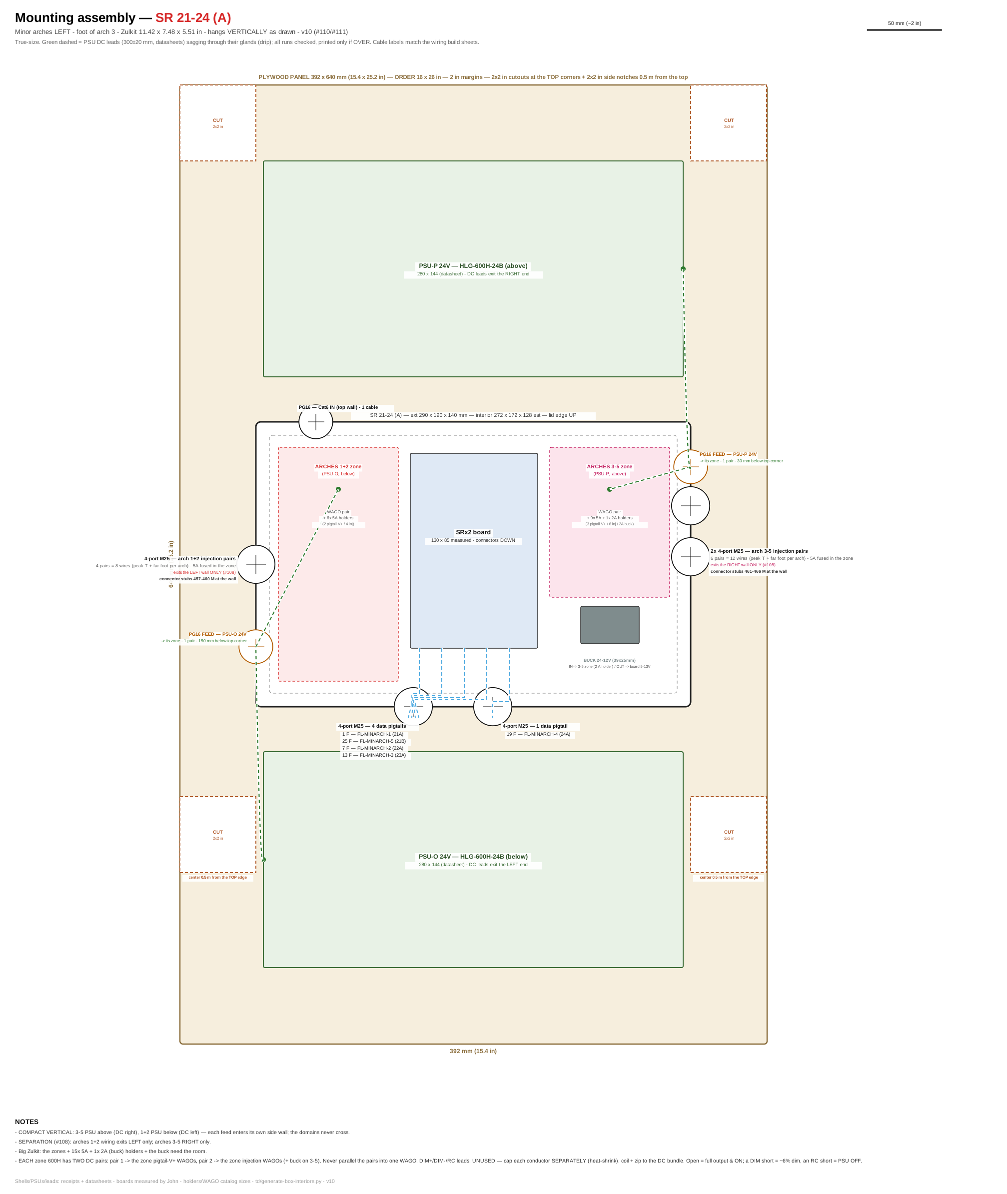
Click for full size. True-size layout of the plywood panel: enclosure placement, PSU positions, DC lead runs (green dashed = drip sag), gland walls with their cable lists, and the dashed CUT squares (2 in margins; 2×2 in top-corner cutouts; 0.5 m side notches on panels over 0.5 m — no cutouts on the major-arch panel). Panel size for every box: plywood cut list.
Sockets — what plugs in. Match the Cable label to the printed tag on each cable.
| Socket on board | Cable label | What it lights | Port | Data (tech) |
|---|---|---|---|---|
| Row ID · No.1 | 1 F FL-MINARCH-1 | Minor arch 1 — right foot (largest, front-most) | 21A | u7 ch1 · 134 px |
| Row ID · No.2 | 7 F FL-MINARCH-2 | Minor arch 2 — right foot | 22A | u9 ch1 · 120 px |
| Row ID · No.3 | 13 F FL-MINARCH-3 | Minor arch 3 — right foot (at SR location) | 23A | u10 ch1 · 108 px |
| Row ID · No.4 | 19 F FL-MINARCH-4 | Minor arch 4 — right foot | 24A | u11 ch1 · 98 px |
| Row ID+1 · No.1 | 25 F FL-MINARCH-5 | Minor arch 5 — right foot (smallest, back-most) | 21B | u7 ch403 · 90 px |
| Row ID+1 · No.2 | — | intentionally empty | 22B | — |
| Row ID+1 · No.3 | — | intentionally empty | 23B | — |
| Row ID+1 · No.4 | — | intentionally empty | 24B | — |
SR 25-28 (A) — Minor Arches — RIGHT side
Where: inner foot of minor arch 3
What this box does: Lights all 5 minor arches on the RIGHT side — one socket per arch, arch 5 on the second row. BOTH minor-arch PSUs (Q + R) mount at this box; ALL arch power runs THROUGH the enclosure.
| Board inside | Falcon SRx2 — ID dial set to A |
| Network in | Short direct Cat6 from the controller (co-located with the front-right tower). Do NOT swap with the left-side Cat6. |
| Board power | PSU Q feeds the ARCHES 1+2 bus, PSU R the ARCHES 3+4+5 bus — two isolated two isolated 24 V WAGO zones inside the box. Board runs on 12 V from the 10 A buck off the 3-5 zone. |
| Fusing | Every V+ line 5 A fused. 3 injection points per arch (data-in foot via the pigtail, peak T, far foot) — no V+ cut. SEPARATION RULE: arches 1-2 lines exit the LEFT wall of the box, arches 3-5 the RIGHT wall. Never mix buses. |
Internal wiring — build sheet
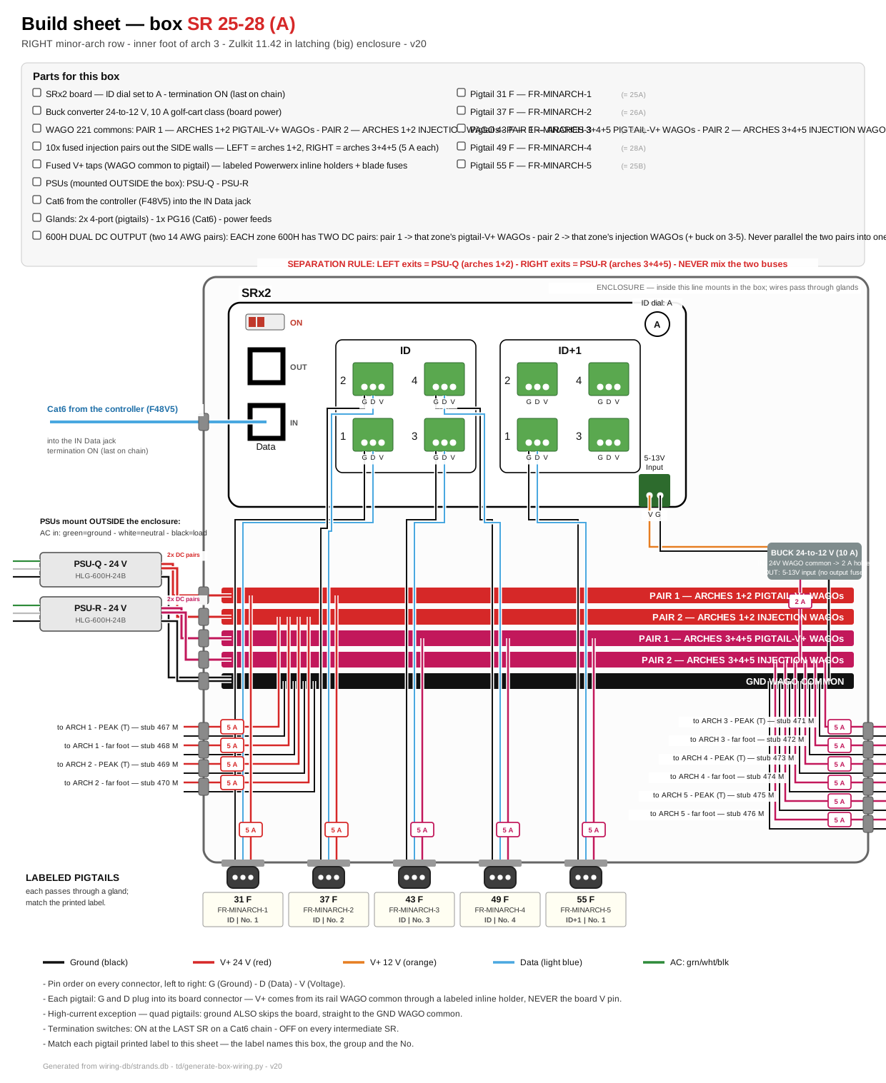
Click for full size. This is the printable installer sheet: parts checklist, board hookups, buses, fuses, and the labeled pigtails for this box.
Mounting assembly — plywood panel, PSUs, gland positions
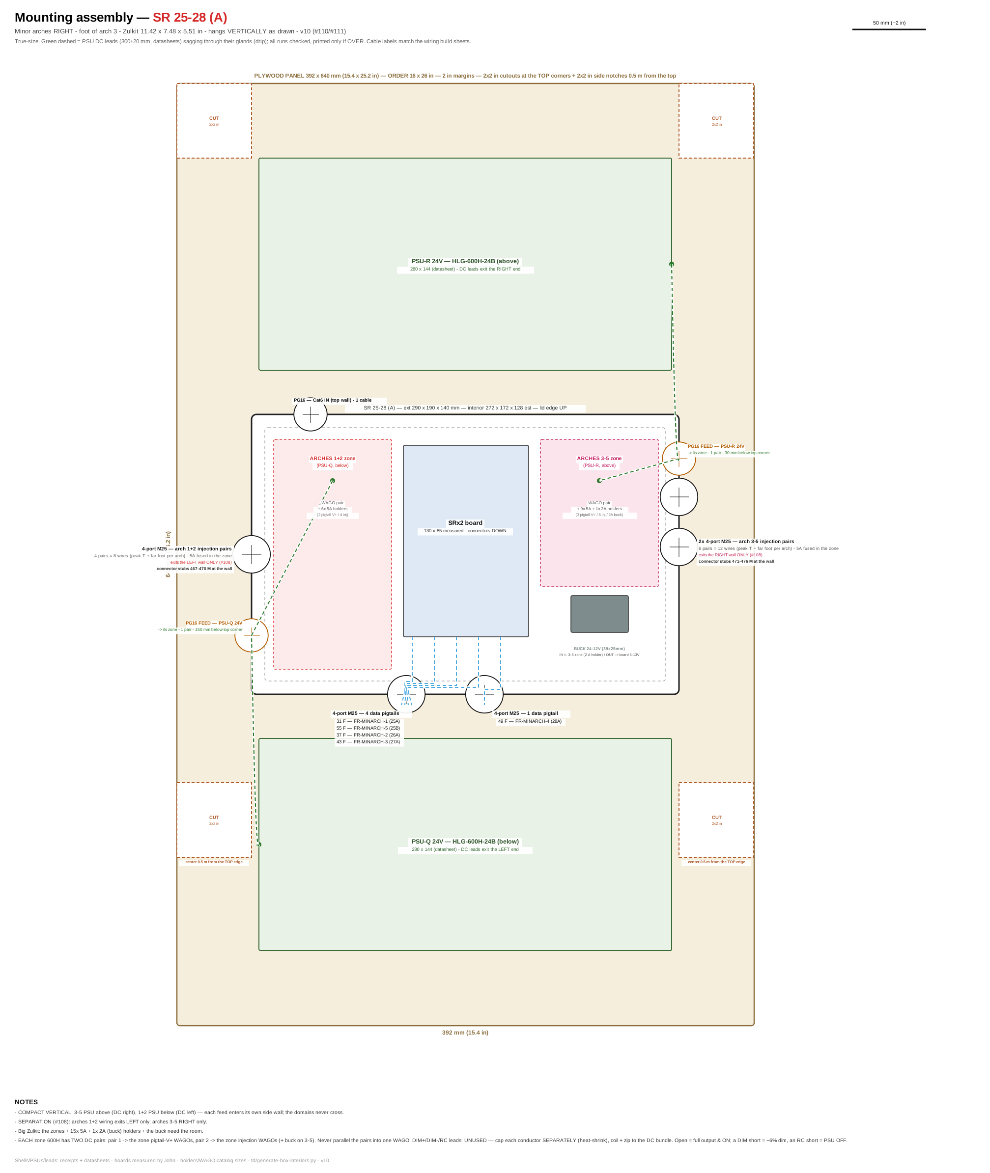
Click for full size. True-size layout of the plywood panel: enclosure placement, PSU positions, DC lead runs (green dashed = drip sag), gland walls with their cable lists, and the dashed CUT squares (2 in margins; 2×2 in top-corner cutouts; 0.5 m side notches on panels over 0.5 m — no cutouts on the major-arch panel). Panel size for every box: plywood cut list.
Sockets — what plugs in. Match the Cable label to the printed tag on each cable.
| Socket on board | Cable label | What it lights | Port | Data (tech) |
|---|---|---|---|---|
| Row ID · No.1 | 31 F FR-MINARCH-1 | Minor arch 1 — right foot (largest, front-most) | 25A | u12 ch1 · 134 px |
| Row ID · No.2 | 37 F FR-MINARCH-2 | Minor arch 2 — right foot | 26A | u14 ch1 · 120 px |
| Row ID · No.3 | 43 F FR-MINARCH-3 | Minor arch 3 — right foot (at SR location) | 27A | u15 ch1 · 108 px |
| Row ID · No.4 | 49 F FR-MINARCH-4 | Minor arch 4 — right foot | 28A | u16 ch1 · 98 px |
| Row ID+1 · No.1 | 55 F FR-MINARCH-5 | Minor arch 5 — right foot (smallest, back-most) | 25B | u12 ch403 · 90 px |
| Row ID+1 · No.2 | — | intentionally empty | 26B | — |
| Row ID+1 · No.3 | — | intentionally empty | 27B | — |
| Row ID+1 · No.4 | — | intentionally empty | 28B | — |
SR 29-32 (A) — Major Arches (entrance)
Where: right foot of major arch 4
What this box does: Lights all 5 major entrance arches — one socket per arch, arch 5 on the second row. Every arch has a V+ CUT at its crown.
| Board inside | Falcon SRx2 — ID dial set to A |
| Network in | Short direct Cat6 from the controller (arch 4 is next to the front-right tower). |
| Board power | PSU-K (arch 4 right foot) feeds a 24 V bus IN this box; the 10 A buck taps it for 12 V board power. Arch 4 data-in V+ rides its SR pigtail from the bus (5 A fused); ONE fused 5 A pair runs out to the arch-4 midway T. |
| Fusing | All other arch V+ joins OUTSIDE this box: every leg has its own PSU (E–N) with a power tap pod splitting to its midway + end-injection Ts, 5 A fused (#106). Remember: V+ cut at every crown, data + GND pass through. |
Internal wiring — build sheet
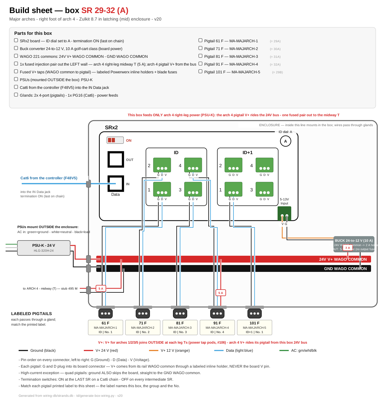
Click for full size. This is the printable installer sheet: parts checklist, board hookups, buses, fuses, and the labeled pigtails for this box.
Mounting assembly — plywood panel, PSUs, gland positions
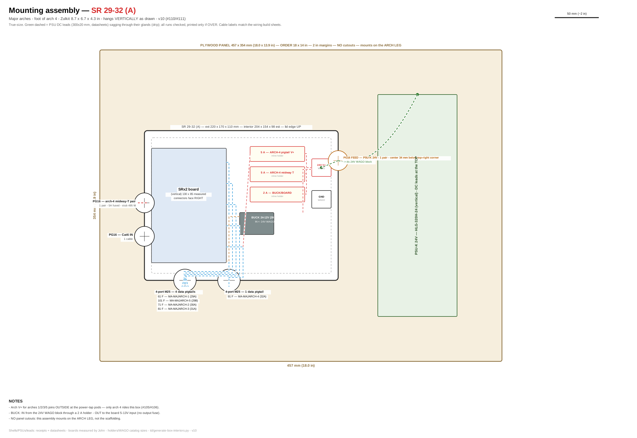
Click for full size. True-size layout of the plywood panel: enclosure placement, PSU positions, DC lead runs (green dashed = drip sag), gland walls with their cable lists, and the dashed CUT squares (2 in margins; 2×2 in top-corner cutouts; 0.5 m side notches on panels over 0.5 m — no cutouts on the major-arch panel). Panel size for every box: plywood cut list.
Sockets — what plugs in. Match the Cable label to the printed tag on each cable.
| Socket on board | Cable label | What it lights | Port | Data (tech) |
|---|---|---|---|---|
| Row ID · No.1 | 61 F MA-MAJARCH-1 | Major arch 1 — right foot (largest, front-most) | 29A | u39 ch1 · 240 px |
| Row ID · No.2 | 71 F MA-MAJARCH-2 | Major arch 2 — right foot | 30A | u41 ch1 · 230 px |
| Row ID · No.3 | 81 F MA-MAJARCH-3 | Major arch 3 — right foot | 31A | u43 ch1 · 230 px |
| Row ID · No.4 | 91 F MA-MAJARCH-4 | Major arch 4 — right foot (at SR location) | 32A | u45 ch1 · 220 px |
| Row ID+1 · No.1 | 101 F MA-MAJARCH-5 | Major arch 5 — right foot (smallest, back-most) | 29B | u47 ch1 · 220 px |
| Row ID+1 · No.2 | — | intentionally empty | 30B | — |
| Row ID+1 · No.3 | — | intentionally empty | 31B | — |
| Row ID+1 · No.4 | — | intentionally empty | 32B | — |
SR 33-36 (A) — Rose Window
Where: window hub (all 4 rose boxes co-locate here)
What this box does: Lights rose petals 1–4 — one petal per socket, 517 LEDs each. This is the ONLY zone where LED power flows through the board (12 V).
| Board inside | Falcon SRx1 — ID dial set to A |
| Network in | Dedicated Cat6 from the controller (ports 33–36), up the tower scaffold to the hub. |
| Board power | Direct 12 V from PSU-A (HLG-320H-12) — no buck converter. The same PSU feeds both ends of each of its 4 petals. |
| Fusing | Near end: petal V+ through the board (within its 5 A fuse at the 50% cap). Far end of every petal: raw 5 A tap (18 AWG) from the same PSU. |
Internal wiring — build sheet
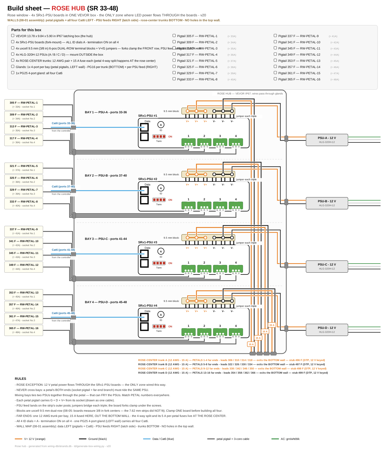
Click for full size. This is the printable installer sheet: parts checklist, board hookups, buses, fuses, and the labeled pigtails for this box.
Download the printable PDF — one Letter page; print it and build. (The PDF regenerates with the sheet — any change to the drawing must also land in the PDF.)
Mounting assembly — plywood panel, PSUs, gland positions
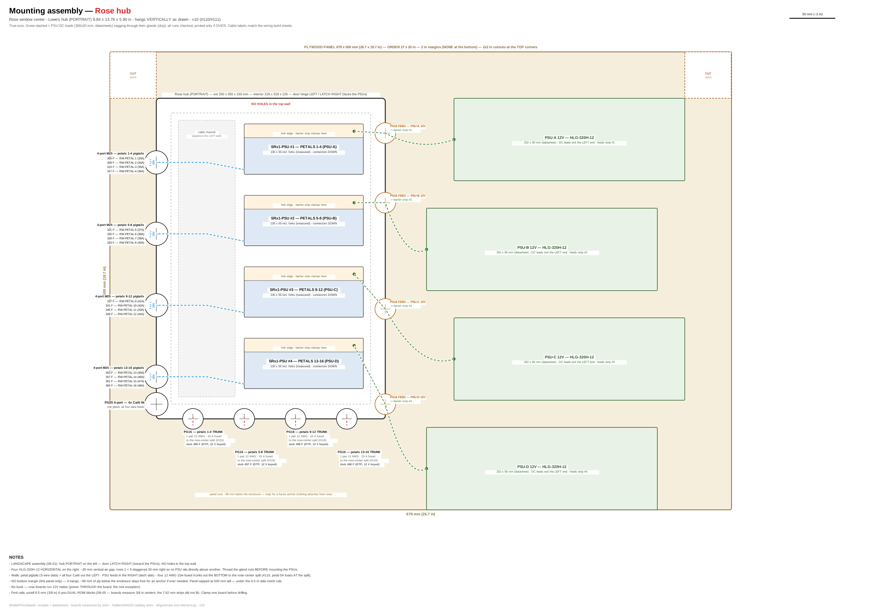
Click for full size. True-size layout of the plywood panel: enclosure placement, PSU positions, DC lead runs (green dashed = drip sag), gland walls with their cable lists, and the dashed CUT squares (2 in margins; 2×2 in top-corner cutouts; 0.5 m side notches on panels over 0.5 m — no cutouts on the major-arch panel). Panel size for every box: plywood cut list.
Sockets — what plugs in. Match the Cable label to the printed tag on each cable.
| Socket on board | Cable label | What it lights | Port | Data (tech) |
|---|---|---|---|---|
| No.1 | 305 F RW-PETAL-1 | Rose petal 1 — one petal per dedicated port (SRx1 #1, PSU-A) | 33A | u76 ch1 · 517 px |
| No.2 | 309 F RW-PETAL-2 | Rose petal 2 — one petal per dedicated port (SRx1 #1, PSU-A) | 34A | u80 ch1 · 517 px |
| No.3 | 313 F RW-PETAL-3 | Rose petal 3 — one petal per dedicated port (SRx1 #1, PSU-A) | 35A | u84 ch1 · 517 px |
| No.4 | 317 F RW-PETAL-4 | Rose petal 4 — one petal per dedicated port (SRx1 #1, PSU-A) | 36A | u88 ch1 · 517 px |
SR 37-40 (A) — Rose Window
Where: window hub (all 4 rose boxes co-locate here)
What this box does: Lights rose petals 5–8 — one petal per socket, 517 LEDs each. This is the ONLY zone where LED power flows through the board (12 V).
| Board inside | Falcon SRx1 — ID dial set to A |
| Network in | Dedicated Cat6 from the controller (ports 37–40), up the tower scaffold to the hub. |
| Board power | Direct 12 V from PSU-B (HLG-320H-12) — no buck converter. The same PSU feeds both ends of each of its 4 petals. |
| Fusing | Near end: petal V+ through the board (within its 5 A fuse at the 50% cap). Far end of every petal: raw 5 A tap (18 AWG) from the same PSU. |
Internal wiring — build sheet
Click for full size. This is the printable installer sheet: parts checklist, board hookups, buses, fuses, and the labeled pigtails for this box.
Download the printable PDF — one Letter page; print it and build. (The PDF regenerates with the sheet — any change to the drawing must also land in the PDF.)
Mounting assembly — plywood panel, PSUs, gland positions
Click for full size. True-size layout of the plywood panel: enclosure placement, PSU positions, DC lead runs (green dashed = drip sag), gland walls with their cable lists, and the dashed CUT squares (2 in margins; 2×2 in top-corner cutouts; 0.5 m side notches on panels over 0.5 m — no cutouts on the major-arch panel). Panel size for every box: plywood cut list.
Sockets — what plugs in. Match the Cable label to the printed tag on each cable.
| Socket on board | Cable label | What it lights | Port | Data (tech) |
|---|---|---|---|---|
| No.1 | 321 F RW-PETAL-5 | Rose petal 5 — one petal per dedicated port (SRx1 #2, PSU-B) | 37A | u92 ch1 · 517 px |
| No.2 | 325 F RW-PETAL-6 | Rose petal 6 — one petal per dedicated port (SRx1 #2, PSU-B) | 38A | u96 ch1 · 517 px |
| No.3 | 329 F RW-PETAL-7 | Rose petal 7 — one petal per dedicated port (SRx1 #2, PSU-B) | 39A | u100 ch1 · 517 px |
| No.4 | 333 F RW-PETAL-8 | Rose petal 8 — one petal per dedicated port (SRx1 #2, PSU-B) | 40A | u104 ch1 · 517 px |
SR 41-44 (A) — Rose Window
Where: window hub (all 4 rose boxes co-locate here)
What this box does: Lights rose petals 9–12 — one petal per socket, 517 LEDs each. This is the ONLY zone where LED power flows through the board (12 V).
| Board inside | Falcon SRx1 — ID dial set to A |
| Network in | Dedicated Cat6 from the controller (ports 41–44), up the tower scaffold to the hub. |
| Board power | Direct 12 V from PSU-C (HLG-320H-12) — no buck converter. The same PSU feeds both ends of each of its 4 petals. |
| Fusing | Near end: petal V+ through the board (within its 5 A fuse at the 50% cap). Far end of every petal: raw 5 A tap (18 AWG) from the same PSU. |
Internal wiring — build sheet
Click for full size. This is the printable installer sheet: parts checklist, board hookups, buses, fuses, and the labeled pigtails for this box.
Download the printable PDF — one Letter page; print it and build. (The PDF regenerates with the sheet — any change to the drawing must also land in the PDF.)
Mounting assembly — plywood panel, PSUs, gland positions
Click for full size. True-size layout of the plywood panel: enclosure placement, PSU positions, DC lead runs (green dashed = drip sag), gland walls with their cable lists, and the dashed CUT squares (2 in margins; 2×2 in top-corner cutouts; 0.5 m side notches on panels over 0.5 m — no cutouts on the major-arch panel). Panel size for every box: plywood cut list.
Sockets — what plugs in. Match the Cable label to the printed tag on each cable.
| Socket on board | Cable label | What it lights | Port | Data (tech) |
|---|---|---|---|---|
| No.1 | 337 F RW-PETAL-9 | Rose petal 9 — one petal per dedicated port (SRx1 #3, PSU-C) | 41A | u108 ch1 · 517 px |
| No.2 | 341 F RW-PETAL-10 | Rose petal 10 — one petal per dedicated port (SRx1 #3, PSU-C) | 42A | u112 ch1 · 517 px |
| No.3 | 345 F RW-PETAL-11 | Rose petal 11 — one petal per dedicated port (SRx1 #3, PSU-C) | 43A | u116 ch1 · 517 px |
| No.4 | 349 F RW-PETAL-12 | Rose petal 12 — one petal per dedicated port (SRx1 #3, PSU-C) | 44A | u120 ch1 · 517 px |
SR 45-48 (A) — Rose Window
Where: window hub (all 4 rose boxes co-locate here)
What this box does: Lights rose petals 13–16 — one petal per socket, 517 LEDs each. This is the ONLY zone where LED power flows through the board (12 V).
| Board inside | Falcon SRx1 — ID dial set to A |
| Network in | Dedicated Cat6 from the controller (ports 45–48), up the tower scaffold to the hub. |
| Board power | Direct 12 V from PSU-D (HLG-320H-12) — no buck converter. The same PSU feeds both ends of each of its 4 petals. |
| Fusing | Near end: petal V+ through the board (within its 5 A fuse at the 50% cap). Far end of every petal: raw 5 A tap (18 AWG) from the same PSU. |
Internal wiring — build sheet
Click for full size. This is the printable installer sheet: parts checklist, board hookups, buses, fuses, and the labeled pigtails for this box.
Download the printable PDF — one Letter page; print it and build. (The PDF regenerates with the sheet — any change to the drawing must also land in the PDF.)
Mounting assembly — plywood panel, PSUs, gland positions
Click for full size. True-size layout of the plywood panel: enclosure placement, PSU positions, DC lead runs (green dashed = drip sag), gland walls with their cable lists, and the dashed CUT squares (2 in margins; 2×2 in top-corner cutouts; 0.5 m side notches on panels over 0.5 m — no cutouts on the major-arch panel). Panel size for every box: plywood cut list.
Sockets — what plugs in. Match the Cable label to the printed tag on each cable.
| Socket on board | Cable label | What it lights | Port | Data (tech) |
|---|---|---|---|---|
| No.1 | 353 F RW-PETAL-13 | Rose petal 13 — one petal per dedicated port (SRx1 #4, PSU-D) | 45A | u124 ch1 · 517 px |
| No.2 | 357 F RW-PETAL-14 | Rose petal 14 — one petal per dedicated port (SRx1 #4, PSU-D) | 46A | u128 ch1 · 517 px |
| No.3 | 361 F RW-PETAL-15 | Rose petal 15 — one petal per dedicated port (SRx1 #4, PSU-D) | 47A | u132 ch1 · 517 px |
| No.4 | 365 F RW-PETAL-16 | Rose petal 16 — one petal per dedicated port (SRx1 #4, PSU-D) | 48A | u136 ch1 · 517 px |