Power Map
Every power supply (PSU): its letter, where it sits, what it feeds, and how hard it works. Rules and sizing rationale live on the Power page; this page is the where-does-the-wire-go view.
As built (finalized before the 2026-08-17 design freeze):
- Dedicated canopy PSUs — PSU-Y (front-right) and PSU-Z (front-left), each an HLG-320H-24, so each front tower’s HLG-600H-24B carries only spire + quad. Installed.
- AC distribution — finalized: 12 AWG outdoor cordage, a 6-circuit spider box plus the generator’s two native 20 A outlets. See the AC distribution chart.
- Aux loads (sound, crew, charging) ride inside the ~1 kW of headroom the 8 kW software budget leaves on the generator.
Load columns: full white is the worst-case sizing number; @ cap was computed under the earlier global 50% cap and is now a conservative floor — the current policy is 80% (rose 70%) with an 8 kW software budget; the Power page is authoritative for policy numbers.
24 V system
Main arches — PSUs E–N (10× HLG-320H-24, at ground level)
One PSU per arch foot; each powers its own leg + curve half at two injection points — the leg’s midway T and its end T (data-in T on right legs). V+ is cut at every crown.
The split from PSU to the two Ts happens in a power tap pod at each foot (mini IP65 box: WAGO split + two sealed 5 A inline fuses) — except arch 4’s right leg: the box IS at that foot, so the data-in V+ simply rides the SR pigtail off the box’s 24 V bus (5 A fused), one fused pair runs out to the midway T, and the same bus feeds the board’s buck (9 pods + 1 in-box split total).
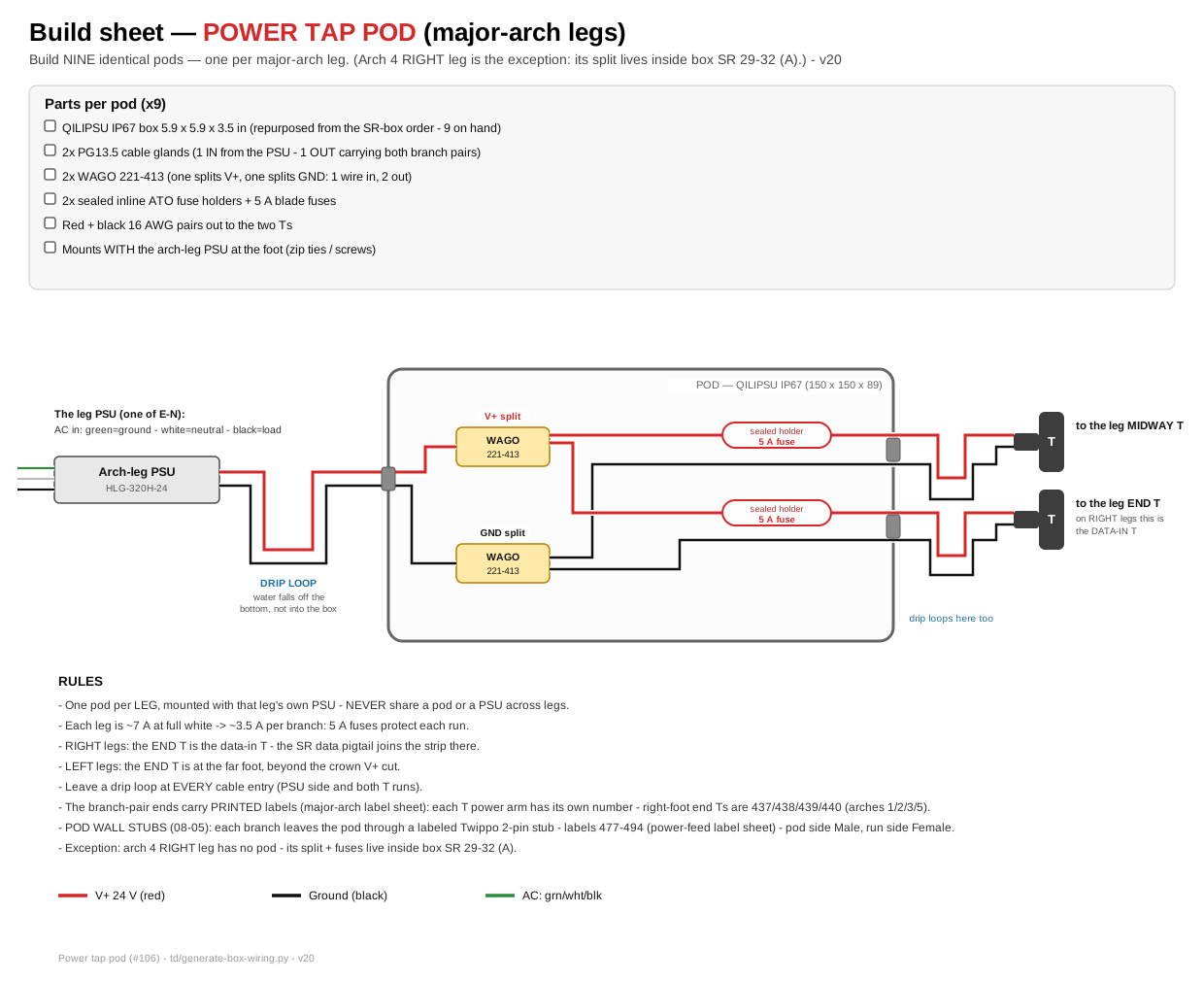
The pod build sheet — click for full size. Build nine identical.
| PSU | Arch / leg | Full white | @ cap |
|---|---|---|---|
| E / F | Arch 1 right / left | 7.2 A | 3.6 A |
| G / H | Arch 2 right / left | 6.9 A | 3.5 A |
| I / J | Arch 3 right / left | 6.9 A | 3.5 A |
| K / L | Arch 4 right / left | 6.6 A | 3.3 A |
| M / N | Arch 5 right / left | 6.6 A | 3.3 A |
Minor arches — PSUs O–R (4× HLG-600H-24B, mounted AT the SR boxes)
Both PSUs of each side mount at that side’s SR box (inner foot of arch 3), and all arch power runs THROUGH the enclosure on two isolated 24 V buses — decided 2026-07-25 (#108):
- ARCHES 1+2 bus (PSU O / Q) — injection lines exit the LEFT wall of the box
- ARCHES 3+4+5 bus (PSU P / R) — injection lines exit the RIGHT wall of the box
- SEPARATION RULE: the two buses never mix — one PSU must never inject into the other’s arches. The build sheets draw the buses in two colors (red / magenta) and force the opposite-side exits.
Three injection points per arch, no V+ cut, all from that arch’s own bus: the data-in foot (V+ rides the SR pigtail), the peak T-connector, and the far foot (power-only pigtail). Every V+ line is 5 A fused in the box (10 injection pairs + 5 pigtails per box).
| PSU | Side | Arches | Full white | @ cap |
|---|---|---|---|---|
| O | LEFT side | 1 + 2 | 15.2 A | 7.6 A |
| P | LEFT side | 3 + 4 + 5 | 17.8 A | 8.9 A |
| Q | RIGHT side | 1 + 2 | 15.2 A | 7.6 A |
| R | RIGHT side | 3 + 4 + 5 | 17.8 A | 8.9 A |
Load check (from the wiring DB): arches 1+2 = 254 px, arches 3+4+5 = 296 px — the split balances the two PSUs (7.6 vs 8.9 A at cap), both far under the 600H’s 25 A even at full white.
Towers — PSUs S–X (6× HLG-600H-24B) + canopy PSUs Y–Z (2× HLG-320H-24), tower-mounted
Front towers: one HLG-600H-24B each (spire + quad) plus a dedicated HLG-320H-24 for canopy (open decision 1 above). Back towers: two HLG-600H-24B each — top (spire + quad-top) vs bottom (quad-bottom).
| PSU | Tower | Feeds | Model | Full white | @ cap |
|---|---|---|---|---|---|
| S | Front-right | Spire + quad arch (chained, both taps) | HLG-600H-24B | ~26.8 A | ~13.4 A |
| Y | Front-right | Canopy only (3 runs) | HLG-320H-24 | ~7.6 A | ~3.8 A |
| T | Front-left | Spire + quad arch (chained, both taps) | HLG-600H-24B | ~26.8 A | ~13.4 A |
| Z | Front-left | Canopy only (3 runs) | HLG-320H-24 | ~7.6 A | ~3.8 A |
| U | Back-right | Spire + back-top quad | HLG-600H-24B | ~16.9 A | ~8.5 A |
| V | Back-right | Back-bottom quad | HLG-600H-24B | 20.1 A | 10.0 A |
| W | Back-left | Spire + back-top quad | HLG-600H-24B | ~16.9 A | ~8.5 A |
| X | Back-left | Back-bottom quad | HLG-600H-24B | 20.1 A | 10.0 A |
⚠ Front towers S/T exceed rating at full white. With the confirmed 1.44 W globe (the spire node is the same 6-LED WS2811 as the canopy), S/T draw ~26.8 A — 107% of the 25 A rating at full white. Moving the canopy onto its own PSU (Y/Z) removes ~7.6 A but does not bring S/T under 25 A; the remaining ~7% is held within rating by the brightness cap / power compressor (#113), which trims the non-arch/non-rose zones first. No PSU up-size is needed as long as the cap or compressor is in the pipeline. (Supersedes the earlier ~23.5 A figure, which used a 0.72 W globe estimate. U/W rose from ~13.7 A for the same reason.)
Every tower enclosure has a fused 24 V bus fed from its tower PSU — that bus, never the SR, powers the LEDs (see the primer).
12 V systems
Rose window — PSUs A–D (4× HLG-320H-12, at the hub — all in hand)
One PSU per rose SR box; each feeds both ends of its 4 petals (near end through the SRx1, far end via a 5 A tap).
| PSU | Box | Petals | Full white | @ cap |
|---|---|---|---|---|
| A | SR 33-36 (A) | 1–4 | 34.4 A* | 17.2 A |
| B | SR 37-40 (A) | 5–8 | 34.4 A* | 17.2 A |
| C | SR 41-44 (A) | 9–12 | 34.4 A* | 17.2 A |
| D | SR 45-48 (A) | 13–16 | 34.4 A* | 17.2 A |
* Above the 26.7 A rating at full white — the rose is why the brightness cap is enforced at the controller port level (hardware ceiling ~74%; mandated global cap 50%). Built-in over-current protection is the backstop.
Flood rail — 4× HLG-185H-12 (tower-mounted) + 2 spares
Spirelets + wash are one 12 V fixture on a dedicated per-tower flood PSU — kept off the SR buck and off the 24 V bus.
| Tower | Fixtures | Load @ 10 W |
|---|---|---|
| Front-right / Front-left | 7 wash + 6 spirelets each | ~11 A each |
| Back-right / Back-left | 4 spirelets each | ~3 A each |
Fuse cheat-sheet
| What | Fuse | Wire |
|---|---|---|
| Quad power tap (each of 2 per big quad; 1 per back-top) | 15 A inline blade | 12 AWG |
| Spire strings (per tower, one group fuse) | 5 A | — |
| Canopy (per run) | 3 A | — |
| Spirelets/wash (12 V rail groups) | 2 A | — |
| Rose far-end tap (per petal) | 5 A inline blade | 18 AWG |
Fuse at the bus/PSU end of every tap. Waterproof ATO/ATC holders (32 V DC). Common ground everywhere — SR GND ↔ PSU GND ↔ fixture GND must be bonded or the data has no reference.
PSU totals (order sheet view)
| Model | Count | Where |
|---|---|---|
| HLG-320H-24 (24 V / 13.3 A) | 12 (+1 spare) | Main arches E–N + canopy Y–Z |
| HLG-600H-24B (24 V / 25 A) | 10 (+1 spare) | Minor arches O–R + towers S–X |
| HLG-320H-12 (12 V / 26.7 A) | 4 — in hand | Rose A–D |
| HLG-185H-12 (12 V / 15 A) | 4 (+2 spares) | Flood rails |
| Total | 30 (+4 spares) |