Power & Wiring — City of Gods 2026
How the condensed folly is driven: which enclosures come out of the workspace, how the four extra fixtures attach, and how the load splits across three circuits.
Boxes vs boards. Throughout this page, a box is a physical enclosure you carry and mount; a board is a Falcon SmartReceiver inside one. They are not the same count — the rose window’s four SRx1 boards all live in a single hub box.
Derived from the wiring database (wiring-db/strands.db) and the Power Map. Where this page and the database disagree, the database wins.
4 boxes, 7 SR boards
You are installing four physical enclosures. Three are single-board boxes; the fourth is the rose hub, which holds four SRx1 boards in one ABS case.
| Enclosure | Boards inside | Drives | Falcon ports |
|---|---|---|---|
Back-left tower box — SR 13-16 (A) | 1 × SRx4 | Back-left spire (8 strands), 5 spirelets (all on 15A), small back-top-left quad | 13–16 |
Back-right tower box — SR 17-20 (A) | 1 × SRx4 | Back-right spire (8 strands), 5 spirelets (all on 19A), small back-top-right quad | 17–20 |
Major arch box — SR 29-32 (A) | 1 × SRx2 | All 5 major arches | 29–32 |
| Rose window hub — one ABS hinged box at the window | 4 × SRx1 — SR 33-36, 37-40, 41-44, 45-48 (all dial A) | All 16 petals, one petal per dedicated port | 33–48 |
| 7 boards total | 28 of 48 ports |
One petal per dedicated port — four petals pooled on one port exceed the 704 px cap by ~3×.
7 Cat6 runs, one per group of four Falcon ports; four land in the rose hub, one per board.
The four add-on fixtures
Two minor arches and two extra spirelets have no board output of their own in this plan.
The spare sockets are not ready to use.
30B,31B,16B,16C,20Band20Care real board outputs, but the build sheets mark them “intentionally empty” — no pigtail is made up. A socket in service carries a numbered tag (e.g.`71 F`); a spare carries “—”. Fitting a pigtail means opening the box.
Each add-on attaches to whatever is physically closest. Two facts decide which mechanism:
- 10 m limit — a pixel-data run beyond 10 m degrades and needs null pixels or a booster (Wiring).
- 🔄 AS BUILT: major arches take data at the LEFT foot, so data-out is the right foot. The crew installed all five mirrored from the design, found on site 2026-10-18. The
SR 29-32 (A)box therefore mounts at the left foot of arch 4 — the same end as the data-ins, opposite the data-outs. All five major arches run Direction = Reverse, because the model has pixel 0 at the right foot on every one of them. - Both minor arches take data at their INNER foot — an install constraint. That is the left arch’s right foot and the right arch’s left foot.
| Fixture | How it attaches | Why | Port load after |
|---|---|---|---|
| Minor arch A — right (134 px) | Chain onto major arch 1’s data-out (right foot) | 0.91 m to the arch’s inner foot. Reverse — mini-right’s pixel 0 is at its outer foot | 29A VS2 · abs 5611 · 374 px on the port |
| Minor arch A — left (134 px) | New pigtail at 32B | box is now on the left side — 3.89 m to the arch’s inner foot. Forward — mini-left’s pixel 0 is its inner foot | 32B · abs 3061 · 354 px on the port |
| Spirelet 9 (1 px) | Chain onto the end of the 15A chain | re-chained 2026-10-17 — all five spirelets on one pigtail; 15D stays zeroed | port 15: 5 px |
| Spirelet 10 (1 px) | Chain onto the end of the 19A chain | ditto; 19D stays zeroed | port 19: 5 px |
All far below the 704 px per-port cap. Runs must be re-measured against the 10 m limit once the layout is fixed — documentation#131.
🔌 SmartReceiver termination
A SmartReceiver must be terminated — DIP switch ON — when it is the LAST board in its chain. This is not a set-and-forget setting: it depends on which build you are running.
On playa both tower boards had an (E) satellite downstream (13E and 17E, the back-bottom quads), so they were not last and termination was OFF. City of Gods drops those satellites, so both tower boards became last in chain and had to be terminated — done on site 2026-10-20. All four boards in this build are now confirmed terminated.
| Board | Playa satellite | City of Gods | Termination |
|---|---|---|---|
| Back-left tower (SRx4) | 13E | none | ON |
| Back-right tower (SRx4) | 17E | none | ON |
| Major arch box (SRx2) | none | none | ON — verified, unchanged since playa |
| Rose hub (4 × SRx1) | none | none | ON — verified, unchanged since playa |
⚠️ Getting this wrong looks like something else. The symptom is a flaky or static data stream across the whole board — indistinguishable at a glance from a damaged Cat6 or a failing controller port. It cost troubleshooting time on the right tower before the real fault was found elsewhere.
Carry this forward: on any reconfiguration, ask for each board whether anything is still downstream of it in this build. Removing a receiver promotes the one above it to last-in-chain.
✅ Controller status — configured 2026-10-18
The Falcon F48V5 at 192.168.8.205 is fully configured and verified for City of Gods: 52/52 active rows match the target, 0 channel overlaps, nothing lit that should be off, 10,497 px, frame end back to 70400.
🛑 Enter Falcon config by hand. Do not script it.
A bulk API replay crashed this board on 2026-10-18 — it rebooted part-way and ports 29–48 lost every row, a loss that persisted through a power cycle. The same thing happened on playa on 2026-08-31, when the folly went dark mid-performance. The cause is still not understood.
| Do | Don’t |
|---|---|
Enter config in http://192.168.8.205/pixelports.html | Run bulk replay scripts against it |
| Verify afterwards with a read-only pull | Assume “it saved” means “it’s right” |
The read-back verification is not optional — on 10-18 it caught a transposed start channel (21241 for 21421, 60 px adrift, no error and no channel overlap) and all 16 rose petals entered on the port row instead of SmartReceiver connector A. Neither would have surfaced until power-on, and both would have looked like a wiring fault rather than a config one.
Correction to earlier notes: the web UI is not dead. The board serves it only gzipped, so a plain
curl404s on pages that exist.pixelports.htmlworks fine in a browser, and its full-table save is reliable.
Certified configs live in the lighting repo under falcon-backups/.
⚡ The chained minor arch — read this before building the cable
The RIGHT minor arch is too far from any SR box for a pigtail, so it chains off the major arch’s data-out through a cable built for the purpose. (It was the LEFT arch until the mirrored install moved the box and the data-outs to the other side.) It is the only non-standard join in the build, and the only one that can fail in a way that looks like something else.
It chains off MAJOR ARCH 1, from what is now its right foot, into the minor arch’s inner foot — a 0.91 m run. On playa the minor arches sat at X −11.069, essentially major arch 2’s plane, and arch 2 was correctly the nearest; the City of Gods move put both at X −12.31 — exactly major arch 1’s plane. The rule was always nearest major arch; only the worked example went stale. Falcon port 29A, virtual string 2, abs 5611, Direction = Reverse — never 30A.
⚠️ Both minor arches are fed at their inner foot, yet their Direction settings differ. Both statements are true at once, because the two pixel maps are not mirror images:
mini-left’s pixel 0 is at its inner foot (Forward), whilemini-right’s pixel 0 is at its outer foot (Reverse). This looks like an error in the table and is not.
Power: one supply, not two
Updated 2026-10-18. The chained minor arch is powered from PSU E, major arch 1’s own right-foot supply, rather than a dedicated minor-arch PSU.
| PSU | E · HLG-320H-24 · 24 V · 13.3 A · at major arch 1’s right foot |
| Feeds | arch 1 right leg (120 px) + the whole right minor arch (134 px) = 254 px |
| At the 80 % cap | 12.3 A of 13.3 A — 92 % |
| At full white | 15.3 A — 115 %, over rating |
| Taps | two, one per minor-arch half, 5 A fuse each at the PSU end |
This retires PSU Q (HLG-600H-24B) from the load-in — one fewer 600 W supply to carry, mount, weatherproof and stagger against GFCI inrush. PSU O stays, feeding the now-pigtailed left minor arch.
⚠️ PSU E is now the tightest 24 V supply on the rig, and the 80 % cap is load-bearing for it. Lowering the cap is safe; raising it is not.
The three rules — rule 1 now matters less
Both fixtures share one supply, so there are no longer two PSUs’ V+ to parallel. The catastrophic version of this mistake is gone. Rule 1 survives as protection coordination, not as a safety rule. Rules 2 and 3 are unchanged, and rule 3 is still the one people drop.
V+ cut · GND continuous · every section fed its own local V+ and GND
| # | Rule | Why |
|---|---|---|
| 1 | Cut V+ in the extension between the major and the minor arch | Keeps each fused tap the only path for its own current. Formerly this was the “two PSUs’ V+ must never be paralleled” rule; with one supply a missed cut now merely creates a second path within that supply. Still do it. The wiring DB marks v_plus_cut_required on segment 2 of all five major arches. |
| 2 | Let GND pass through the extension | This is the reference bond that gives the single-ended pixel data its reference. It carries signal-level current only. |
| 3 | Feed the minor arch its own V+ and GND from PSU E, at both its injection points | This is the rule that is easy to drop. FL-MINARCH-1 already has two power injection points in the DB — use them. Each half is 67 px = 4.05 A full white, so 5 A per tap is correctly sized. The outer-foot run is 4.61 m and the T does not provide it. |
The junction, drawn
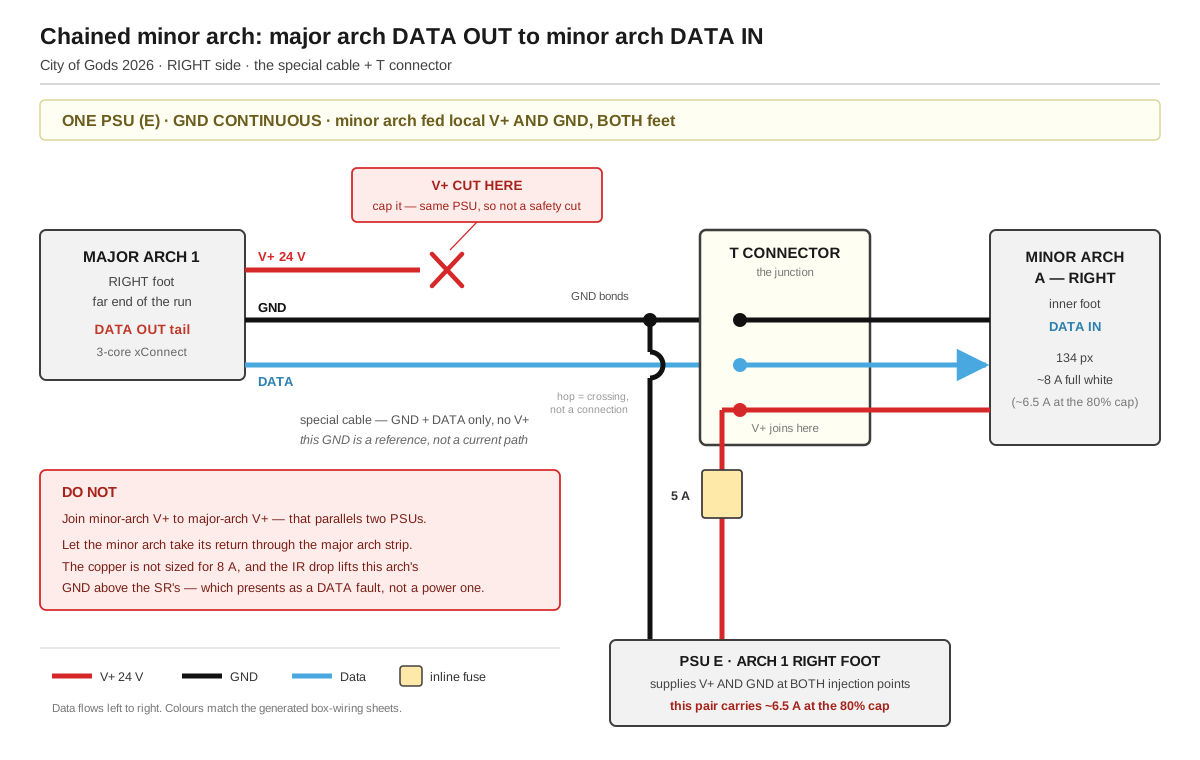
Click for full size. Labels updated 2026-10-18 for major arch 1 and PSU F; the topology drawn is unchanged and still correct, because only the source of V+/GND moved.
Building the special cable
Parts
| xConnect extension, major arch 1 right foot → right minor arch inner foot | 1, cut to the measured run (~0.91 m; keep under 10 m) |
| 3-way xConnect T | 1 |
| Inline fuse holder + 5 A blade fuse | 2 — one per injection point |
V+/GND run, PSU E → minor arch outer foot | 1, 4.61 m plus routing |
| Heat-shrink / end cap for the severed V+ | 1 |
Steps
- Measure the real run first, major arch 1’s right foot to the right minor arch’s inner foot (expect ~0.91 m — they are coplanar). Over 10 m and this plan changes — come back before building.
- Make up the extension carrying GND and DATA only. At the major-arch end, cut the V+ conductor and cap it — unterminated and insulated, so it cannot touch anything.
- Land the extension on the T’s input leg.
- Bring
PSU E’s V+ and GND to the T’s second leg, V+ through a 5 A inline fuse, fused at the PSU end of the run. - The T’s output leg goes to the minor arch data-in at its inner foot: V+ from
PSU E, GND bonded, DATA from major arch 1. The T’s output leg is Female — the arch’s data-in is Male. - Run the second tap —
PSU EV+ (through its own 5 A fuse) and GND out to the minor arch’s outer foot, 4.61 m. This is a separate cable; the T does not cover it. Skip it and you get exactly the failure described below.
Before powering up
- Continuity: major-arch GND is connected through to minor-arch GND
- Continuity: major-arch V+ is not connected to anything — confirm the cut
- Resistance check between minor-arch V+ and major-arch V+ reads open
- Fuse is on the PSU end of the V+ run, not the fixture end
- Both injection points are landed and fused — inner foot via the T, outer foot via its own 4.61 m run
- Power up
PSU Efirst, then confirm the arch lights with correct colour before trusting the chain - Falcon: the chained arch is
29AVS2 at 5611/134 px, Reverse — not30A, and not 3061 (that is the left arch on32B)
If the minor arch shows the right colours but flickers or drops pixels, suspect the ground reference before suspecting data — that is the signature of the failure described below.
Why rule 3 is not optional. Minor arch A is 134 px ≈ 8 A at full white (~6.5 A at the 80 % cap). Without a local GND return, that current would travel back up the extension and through the whole major arch strip — all 240 px of it — to reach the major arch’s injection points. Strip copper is not sized for that; it is precisely why the arches need multiple injection points for their own current. The IR drop along that path would also lift the minor arch’s GND above the SR’s, and that offset is the data-reference failure — the same glitch arriving by a different door.
Grounding “through the LED strip” is therefore adequate as a reference and inadequate as a return. Both jobs have to be satisfied, by different conductors.
The same logic governs the arch legs themselves: V+ is cut at every crown while data and GND pass through, so the strip’s GND conductor bonds the leg PSUs while each leg’s own tap carries its current. Preserve that when the injection points are re-planned for the condensed geometry.
Power
Three 20 A / 120 V circuits. A 20 A circuit allows 16 A / 1,920 W continuous (the 80 % rule). Figures below are full white, the worst case — the mandated 50 % brightness cap halves them in practice. AC watts = LED watts ÷ 0.91 PSU efficiency.
| Circuit | Carries | PSUs | LED W | AC W | Amps |
|---|---|---|---|---|---|
| 1 — Rose | Rose window, all 16 petals | 4× HLG-320H-12 (A–D) | 1,651 | 1,815 | 15.1 A |
| 2 — Major arches + right minor | All 5 major arches, both legs each, + the right minor arch on PSU E | 10× HLG-320H-24 (E–N) | 1,836 | 2,018 | 16.8 A ⚠️ |
| 3 — Towers & left minor | 2 spires, 2 three-face quads, 1 minor arch, 10 spirelets | 2× HLG-600H-24B (U, W) + 1× minor-arch (O) + 1× HLG-185H-12 | 1,101 | 1,210 | 10.1 A |
| 4,588 | 5,042 | 42.0 A |
Why this grouping: each circuit is one coherent failure domain. Lose circuit 1 and the arches still run; lose circuit 2 and the rose still runs. At the 80 % cap the real draw is 13.5 A on circuit 2 and 8.1 A on circuit 3, inside the 16 A continuous allowance.
⚠️ Circuit 2 no longer has full-white headroom — 16.8 A against 16 A continuous. It now relies on the brightness cap, as the rose always has. To get that headroom back, move PSU E to circuit 3 (→ 13.4 A / 13.5 A), at the cost of circuit 2 no longer being exactly “all the major arches”.
Outdoor install
Not weatherproof — needs a plan:
| Item | What it needs |
|---|---|
| Falcon F48V5 | weatherproof enclosure or a sheltered position |
| FPP Pi (+ spare) | same |
| AC distribution | GFCI required, weather-resistant outlets and covers |
| Cat6 and pixel-data joints | drip loops; joints off the ground |
| Cable runs on the ground | matting or ramps; route out of puddles |
- Wind loading — the rose is a large sail area. Rigging and ballast need structural sign-off.
Rules that still apply
- ⚡ Stagger the power-up. Mean Well HLG supplies have high inrush. Ten on circuit 2 switched together can trip a 20 A breaker on make — and a GFCI trips more easily still. Bring them up in groups or use a sequenced distro, and test the sequence through the actual outdoor GFCI before show day.
- The 50 % brightness cap is mandatory. The rose PSUs sit above their rating at full white by design — the cap is what keeps them inside it.
-
Common ground — DC side, per enclosure. Not an AC question. Mean Well HLG outputs are isolated: DC V− floats with respect to AC earth, so mains ground is not what references the data.
Link Signalling Shared ground needed? Falcon → SR, over Cat6 differential, RS-485 style No — tolerant of ground offset SR → fixture, 3-pin pigtail single-ended Yes — data is referenced to fixture GND The bond that matters is inside each enclosure: PSU V−, SR GND and fixture GND on one bus. Getting it wrong works on the bench and glitches on site. Chained fixtures: see above. Open: documentation#107.
- Fuse at the bus/PSU end of every tap. See the Power Map fuse cheat-sheet.